Thanks Mark. No, I really don't know that it was hit by lightning. Probably more likely was that something minor crapped out in the PS and then some ham-handed repairman shorted out a switching FET drain with a screwdriver while poking around, taking it out and other parts too. I yanked the supply out of the scope to remove potential load problems and I'll test for load problems before putting the repaired PS back in. I'll do more battle this afternoon…
So what’s this about a Tek display room?
So what’s this about a Tek display room?
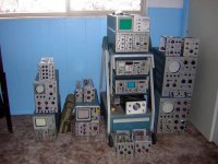
I do need to get it organized a little better but..... at least they are all restored and working. Note the very rare 1K20 spectrum analyzer living in the 535a🙂. There is also a 465B and 2XX series storage scope in the van and a 7603a at work on the audio bench.
Mark
Mark
Attachments
Brian Beck said:
<snip>
EDIT: To add an answer to your question about wiring the two grid pins. Out of habit, I always wire all pins on any tube with multiple grid or cathode leads to reduce inductance. This may be totally unnecessary in most audio applications, but why not do it anyway since it adds little or no cost? If you do add a stopper, try a 200 ohm resistor in each grid lead with the input ends tied together. That gives you 100 ohms with lowered inductance.
I used 200R metal film on all 4 pins of my 5842 driver in one of my amps, which is what most will recommend. I tried "bending the rules" (read: became lazy) on my headphone amp where I just tied all grid pins together, and works just as fine. I did this for my 12B4 preamp too.
ps.
I do have 1M grid leak on my 12B4.
Gridstopper issues
Arnold, Brian, Thanks for the helpful advice. I tried adding a 1M resistor, as Brian suggested, but unfortunately I still have the noise problem. Any other ideas?
To follow up on Brian's questions, I am using short (3" or less) unshielded wires from the volume control to the grid pins. The connecting wires are in free air so there's little extra capacitance added by the chassis ground. I haven't tried a ferrite bead.
You're right about the cathode bypass cap. I tried it at first but preferred the sound without it. I realize the output Z is higher, but this doesn't seem to be a problem in my setup.
Any other suggestions would be most appreciated. I am still puzzled why the 12B4 would mind having its grid shorted to ground. Arnold's experience suggests that a different pot might help. I'm using an Alps Black Beauty right now, which I prefer sonically to the other pots in my parts box. Before I try another pot, I think I want to try putting a 100R in the ground leg of each channel of the pot. This would presumably solve the noise issue and with perhaps less effect on the sound than a gridstopper. Of course, I woun't be able to turn the volume control down completely.
Dave
Re: Gridstopper issues
Fourth down, long yardage. Punt. (Sorry, Stupid Bowl still on my mind)
At this point it’s hard to say, but perhaps you are experiencing oscillations. Maybe you will need a stopper or a bead. Do you have a fast scope on which to observe the output? How is the plate load positioned, and your cathode load? How is B+ bypassed? Grounding? Got a picture of your layout?
Salectric said:Any other ideas?
Fourth down, long yardage. Punt. (Sorry, Stupid Bowl still on my mind)
At this point it’s hard to say, but perhaps you are experiencing oscillations. Maybe you will need a stopper or a bead. Do you have a fast scope on which to observe the output? How is the plate load positioned, and your cathode load? How is B+ bypassed? Grounding? Got a picture of your layout?
Anybody know what happened to Mark A. Gulbrandsen's identity here? His avatar and postings have vanished and a note says that he's on my IGNORE list, which he's not! I checked this site on another computer that didn't have my password and cookies stored on it and it's the same way, so I figured everyone must see him as vanished. I mention it in this thread because he posted a lot on it.
It's part of the server issues we've been having. AudioFreak is aware of the issue and will apply a tourniquet where necessary.
That tourniquet must be applied to Mark's neck. That is what he gets for defecting from the Aleph amps, chip amps, Tripath amps, Bel Canto amps, BAT amps to his beloved boat anchor Krells.
When he gets back on Brian, he will be posting on this thread his CAD diagram for the top plate and back plate of a suggested idea for our 12B4 linestage. We are hoping you guys have some suggestions on it.
Lyndon
When he gets back on Brian, he will be posting on this thread his CAD diagram for the top plate and back plate of a suggested idea for our 12B4 linestage. We are hoping you guys have some suggestions on it.
Lyndon
Zen Mod said:
btw-you really waste energy there burnin' 30mA in 6K25 anode resistor...
what you need is one nice plate choke ,and-tnx to low Ri of 12B4,that choke must not be enormous....in that case Ub will be around 150V,and just one OD will do the beeeezzzznissssss...
I'm not talking here about heat and pennies for electricity bill.....this is more measure of signal energy preservation.
Newbie here, how do I use a plate choke for this circuit?
Do I need to lower B+ and what should be the inductance of the plate choke? thanks.
alexg said:
Newbie here, how do I use a plate choke for this circuit?
Do I need to lower B+ and what should be the inductance of the plate choke? thanks.
The plate choke replaces the anode resistor, I used one of 100H. As the dcr of the choke is much less than a resistor, you need to lower your B+, I am using 150V.
pengboon said:
The plate choke replaces the anode resistor, I used one of 100H. As the dcr of the choke is much less than a resistor, you need to lower your B+, I am using 150V.
Thanks, that is similar to what I was thinking, 120H plate choke and B+ of 150 regulated using an 0D3 for both channels.
alexg said:
Thanks, that is similar to what I was thinking, 120H plate choke and B+ of 150 regulated using an 0D3 for both channels.
That should work very well!
😀
CCS plate loaded 12B4 linestage
Hi,
I modified my 12B4-linestage, substituted the 6K-resistive anode load I used before with a Current source.
I like very much what I am hearing! Much smoother than before, better channel separation.
I did not like an elctrolytic cap as Cathode bypass (I tried it), it is not neccesary though.
Piero

CCS plate loaded 12B4 linestage
sorry one mistake in the diagramm!
there are two 100 Ohm resistors at the top end of the current source connected in parallel = 50 Ohm, setting the current to 20mA!
sorry one mistake in the diagramm!
there are two 100 Ohm resistors at the top end of the current source connected in parallel = 50 Ohm, setting the current to 20mA!
Mark A. Gulbrandsen said:OK, I finally have a power supply combination that works unbelievably well and sounds great! I had been running my 12B4 on an Eico tube regulated bench supply all these months and there was always a small hint of hum and noise in the speakers if you put your ears right up to them. Recently LuckyLyndy and found an interesting H-V regulator board thats made in GErmany by Thel Audio World Audio in Staufenerg Germany. Cost of the board was about 80.00 US Dollars delivered. It comes fully assembl;ed. This regulator board uses an IRFPG50 as the pass device. Its driven by a pretty conventional driver transistor/zener type circuit. Voltage is set with a 10 turn pot. The nice part about this board is that it will accept either DC 100 to 400 volts input, or AC 80 to 320 volts. Its rated at 100ma maximum and I am drawing about 60 ma through it and it gets just a tad bit warm after several hours opaeration. While I won't post the schematic here I might be inclined to scan it and e-mail it to anyone interested.
At any rate it got rid of every last bit of noise form my 12B4 line stage and the stage seems to have improved in many aspects to boot. The S/N has got to be around 90db plus now! The bottom end does seem a tad bit deeper and more refinedl. The midrange is still glorious and the highs seem cleaner and even more refined than they were without it. Needless to say adding this solid state regulator did not change the overall character of the sound, it improved it without doubt!
It wold be easy tio breadboard this circuit.... but even so the assembled version is even a good deal!!
Thanks to Promethius for getting and mailing these regulator boards to us!!
Mark
hi mark,
is it possible that you post the circuit of the here ?
vmps
Vmps:
If I may speak for Mark, he is on assignment in Wyoming, and won't be back until sometime next week. Not really a bad job, because the fall weather is coming early out here, and it must be beautiful up north.
I'll mention to him to check the forums when he gets back.
Lyndon
Salt Lake City
If I may speak for Mark, he is on assignment in Wyoming, and won't be back until sometime next week. Not really a bad job, because the fall weather is coming early out here, and it must be beautiful up north.
I'll mention to him to check the forums when he gets back.
Lyndon
Salt Lake City
LuckyLyndy said:Vmps:
If I may speak for Mark, he is on assignment in Wyoming, and won't be back until sometime next week. Not really a bad job, because the fall weather is coming early out here, and it must be beautiful up north.
I'll mention to him to check the forums when he gets back.
Lyndon
Salt Lake City
thanks
i be waiting
vmps
- Home
- Amplifiers
- Tubes / Valves
- Yet another 12B4 line stage, or is the 12B4 better than the Grounded Grid.....