Hi, I just finished assembling the F4 depot(one pair output transistors 8.5W) I kindly ask if I can match it to the Aikido LV 48V preamp with e88cc (I have 4 from an old SRPP) instead of ecc99 and, if so, what do I have to change in the relative circuit? Thanks in advance for your help
1. better in Tube forum
2. if you insist here, and it applies everywhere, do your homework - present reference schematics and additional info; it is not just polite, it is also preventing misunderstanding and errors in referencing
2. if you insist here, and it applies everywhere, do your homework - present reference schematics and additional info; it is not just polite, it is also preventing misunderstanding and errors in referencing
Hello @sergiog , I recommend you check post #1 ; this thread is ONLY about the black PCB daughter card shown below, which uses tightly matched bipolar transistors. It mounts above a standard FirstWatt F4 circuit board from the diyAudio Store. As @Zen Mod suggests, your inquiries might be a better fit in a different forum.

I find it hard to get the c4 and c5 ceramics. Smd is easy but through hole not so. How critical are the values of 27pf and 2.2 uF? And are other types of caps 'allowed' ?
Thanks for your attention
Leo
Thanks for your attention
Leo
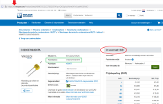
The 27 pF "NP0/C0G" ceramic capacitor labeled "C5" in the first post of this thread, is absolutely criticial. It needs to have the highest quality Class 1 dielectric, named NP0/C0G, and it needs to be 27 pF with tolerance preferably 2% or better. This is the frequency compensation capacitor; working with R16, C5 determines the unity gain crossover frequency and the slew rate. If C5's value is wrong, the amplifier is likely to become unstable and break into oscillation. Fortunately there are several examples which appear to be in stock at DigiKey's Netherlands website:
DigiKey Netherlands (link 1) - - - 200 volt rating, 2%
DigiKey Netherlands (link 2) - - - 250 volt rating, 1%
DigiKey Netherlands (link 3) - - - different company, 1%
The 2.2uF ceramic capacitor labeled C4 is not as crucial as C5. That's why I specified the Class 2 dielectric material "X7R" for C4; in its operation as a smoothing or "bypass" capacitor on the pure DC signal node called NBIAS, C4 experiences constant voltage and so the cheaper X7R material will work acceptably well. C4 need not be exactly 2.2uF for the circuit to function; any capacitance between 2.0uF and 10uF would be acceptable. However, the PCB footprint requires an X7R capacitor whose body is smaller than ~ 2mm x 4.5mm, with a lead spacing of 5.0 mm or 5.08 mm. You'll discover that the lowest price occurs at the lowest capacitance, namely 2.2 microfarads.
Fortunately there are several examples which appear to be in stock at DigiKey's Netherlands website:
DigiKey Netherlands (link 4) - - - TDK General Purpose
DigiKey Netherlands (link 5) - - - TDK Automotive Grade
DigiKey Netherlands (link 6) - - - Murata
It took even far less than 10 minutes. Thanks again. The amount of support and advice that I receive on this great forum is amazing. Must be one of the nicest places on the web. Just great!
After the preamplifier inputs a square wave signal (1v 1kHz), the oscilloscope shows an overshoot phenomenon. Why does this happen? How to deal with it? Thanks to those who provided answers.


I always test with a load. Mark says "Don't drive a load impedance less than about 25 Kohms" in post #1. So something between 25K and 100K seems reasonable. I guess increasing the value of C5 would reduce overshoot but I haven't heard of anyone needing to mess with the compensation...
Thanks for the reply. My question is that the input impedance of a general oscilloscope is usually 1MΩ or higher. Why do I need to add a load resistor when testing a preamplifier? However, I will still add a load resistor (50k 1/4w) to test.
Let me report the follow-up test results to everyone.
A resistor (47k ohms) load is added to the output end of the preamplifier.
The input signal is a square wave (1v) with frequencies of 1kHz, 100kHz and 50Hz.
The test results are as follows:


A resistor (47k ohms) load is added to the output end of the preamplifier.
The input signal is a square wave (1v) with frequencies of 1kHz, 100kHz and 50Hz.
The test results are as follows:
- Home
- Amplifiers
- Pass Labs
- Yes It Can Drive An F4 -- an example circuit using tightly matched bipolar transistors
