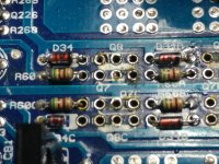
I'm ordering some new diodes for the driver section of the power supply but for the life of me I can't make out the numbers on the diodes and finding it on the schematic is proving tough also. The diodes i'm referring to is D34/D34A/D34B/D34C. In the pic you can see that D34C is broken in half.
I know the value of the resistors. Am I suppose to measure the length/width when searching for them on Digikey? They come in many sizes.
I know the value of the resistors. Am I suppose to measure the length/width when searching for them on Digikey? They come in many sizes.
Attachments
Does either end of the diode connect to ground?
If so, they could be 9 or 10v zeners. The 10v is more common in newer designs.
Service manual, eprom result list | Elektrotanya
If so, they could be 9 or 10v zeners. The 10v is more common in newer designs.
Service manual, eprom result list | Elektrotanya
Attachments
Last edited:
one end does connect to ground. Newer as in beginning what year? Date on the board is 2007.03 REV #0
I thought the XXV series was manufactured much earlier than 2007, but I could be showing my age!
I thought the XXV series was manufactured much earlier than 2007, but I could be showing my age!
I'm not sure where the change was made. The components in your amp more closely match the diagram I posted. The 'older' diagram I have (can't post) uses the components in the attached diagram.
I'd use the 10v, especially if the components in your amp are more like the 4000 diagram.
I'd use the 10v, especially if the components in your amp are more like the 4000 diagram.
what about other options like max wattage and tolerance of the diode? I'm not certain what is going to determine these factors. The only lettering I can make out on the diode is "ST" and "41". I'm scrounging Digikey at the moment

For no particular reason, I never used the 900 series diodes. I always use the 1n52.. or 1n47.. The one you chose should be equally good.
The following will work but the 41 may mean that it's a 1N5241, an 11v Zener.
Blocked
The watt rating of devices like resistors, diodes, small transistors... is typically based on size. Size typically determines surface area and surface area determines the ability to dissipate heat.
The tolerance for the B-suffix diodes (fairly standard) is ±5%.
i went with what you suggested. The parts came in but the resistors are bigger than what's on the board. When ordering resistors I got the color code and I wasn't sure about the other options. What other options should i look for when ordering these parts to make sure i get the right ones?
how do you desolder and solder the areas that require large amounts of solder? Even with my iron at max temp it's difficult to get the solder to flow and join enough where I'm sure it's a good connection
If you can tin the tip, it should. If the tip won't tin, it probably won't conduct heat well enough.
If you have a store that sells tools for stained glass or sheet-metal work, they should have something.
If you have a store that sells tools for stained glass or sheet-metal work, they should have something.
this one did the trick very well
https://www.ebay.com/itm/114294363308
i'm still having trouble reading the AQ20 schematic, i'll be starting classes 9/12 for electrical engineerinig hoping to further my knowledge on diagnosing and repairing
https://www.ebay.com/itm/114294363308
i'm still having trouble reading the AQ20 schematic, i'll be starting classes 9/12 for electrical engineerinig hoping to further my knowledge on diagnosing and repairing
Expect a lot of math and theory with very little regarding repair work.
What are you having trouble understanding?
What are you having trouble understanding?
I know where the audio(supply) drivers are on the board and schematic, but i don't understand how they are connected so as to make sure nothing is shorted or connected wrong. There are many solder points around the legs and burnt traces so i'm having to make bridges.
For example, the pic in post #21, Q8 and Q7, on the back side of the board the supply(1st leg) on both are connected/crossed with D34 and R60, and i can see the middle leg is connected to the trace above and below Q7/Q8, but I don't see a connection on either side of the board for the 3rd leg
For example, the pic in post #21, Q8 and Q7, on the back side of the board the supply(1st leg) on both are connected/crossed with D34 and R60, and i can see the middle leg is connected to the trace above and below Q7/Q8, but I don't see a connection on either side of the board for the 3rd leg
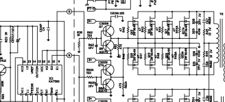
The attached diagram is closer to what you have. The point where the Zener and the 510 ohm resistor connect goes to both the NPN and the PNP transistor bases.
If you have to make a jumper, use wire to make the connection. Don't bridge it with solder alone.
If you have to make a jumper, use wire to make the connection. Don't bridge it with solder alone.
Attachments
thanks. i've been clipping the legs from junk components to make bridges, i assume that's fine or should i use a shielded wire?
- Home
- General Interest
- Car Audio
- XXV Sampson power up issues