The connections to the 494 aren't supposed to be to a particular pin, I assume.
The emitter outputs don't connect to the other EF pair. They drive their own individual groups of FETs.
What is it that you can't read about the diagram? Reading it is not complex. Understanding how a circuit functions can be more difficult. The connections, not so much.
The emitter outputs don't connect to the other EF pair. They drive their own individual groups of FETs.
What is it that you can't read about the diagram? Reading it is not complex. Understanding how a circuit functions can be more difficult. The connections, not so much.
the connections to the 494 itself are important, not meant to specify to any individual pin and the emitter outputs were joined in the drawing just to simplify, it's not to say they actually join in the circuit
i've got all of the supply drivers back in and connected i believe the way they should be, the amp powers up and output relays click
Did you load the FET locations and confirm that all drive signals were good before installing the FETs? It's not a big deal if you didn't but it's a good/safe way to check the drive.
Are you 100% sure that the connections to those transistors are solid? You know that this amp is likely to take a beating from the bass.
Are you 100% sure that the connections to those transistors are solid? You know that this amp is likely to take a beating from the bass.
i checked voltage at each FET and they all were good and stopped there. Still need to check the signals, still need to install my scope software. It's a pc based scope so i'm not sure how reliable the readings will be. It's that or my dso nano v2 or v3
Are the FETs in it yet?
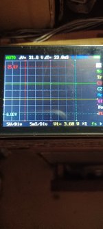
To test the scope, probe one of the output terminals of the driver IC and post the image. Set the scope to 5v/div and 10ms.
To test the scope, probe one of the output terminals of the driver IC and post the image. Set the scope to 5v/div and 10ms.
no FETs are in it yet. I was just about to take a pic and the scope died so it's charging now. Each center leg location for the FETs read the same so i'm hoping that's a good thing.
If you have the tutorial, refer to TT9, item #23. If not, let me know and I'll explain here.
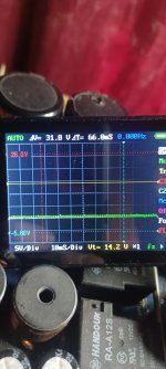
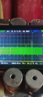
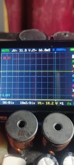
That's nothing. You couldn't get 5v+ on a meter from that. With the same ground, touch the probe to the B+ terminal of the amp and post a photo.
That's nothing. You couldn't get 5v+ on a meter from that. With the same ground, touch the probe to the B+ terminal of the amp and post a photo.
I adjusted everything I could but couldn't get anything besides a flat signal, changing the time/div did nothing either, this is grounded on amp ground and probe to amp +. I tried both of my pocket scopes and got the same results. The switch on the probe set to x1. I've tried to send this all day but for some reason i couldn't reach the site


one more thing, how do i know when dc coupling is set on this scope? There is no setting in the functions to activate it. It's a DSO v201 by Seeed Studio
If you are on DC coupling, the trace will deflect up, off of the ground reference.
You are looking for a lock on the waveform, not on B+. Post a working link to the owner's manual for that scope and I'll try to find it.
The site has been down most of the day.
You are looking for a lock on the waveform, not on B+. Post a working link to the owner's manual for that scope and I'll try to find it.
The site has been down most of the day.
- Home
- General Interest
- Car Audio
- XXV Sampson power up issues


