right, the power supply driver transistors, the ktc3228/kta1275. The via's were pulled out and solder pads were gone so I had to jumper them to the nearest reference point. I have looked into repair kits to replace bad traces, solder pads, and throughholes.
Last edited:
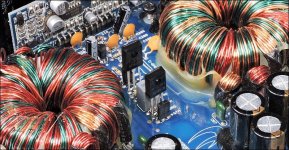
if you refer back to post #5 in the first pic it shows those rods that run over the top of the driver transistors. I'm unable to go any higher
The extra length isn't ideal but if you have no other way to make the connection, I guess it will have to suffice.
Are these the ground/collectors for the PNP driver transistors?
Do you get good drive signals up to the solder pads for the PS FETs?
Are these the ground/collectors for the PNP driver transistors?
Do you get good drive signals up to the solder pads for the PS FETs?
Yes they are the collectors for the KTA1275 PNP's. I'll check the signals tomorrow, got a Dr. appt need to rest up for
Can you solder a short length of wire to the top of the board, feed it through the board and solder it and the lead of the driver together?
How about jumping to the adjacent/hearest PNP driver collector on top or bottom of the board?
How about jumping to the adjacent/hearest PNP driver collector on top or bottom of the board?
i saw where someone had done that before. I'm gonna try to find another way to do it. When you ask if i'm getting good signal up to the solder pads for the PS FETs, do you mean as in square wave? I get a not so good square at the source pad.
There should be no signal on the source of the PS FETs. That's ground.
Are the PS FETs in the board, or not?
Do you have a small capacitor in the range of 0.01uf and 0.1uf?
Are the PS FETs in the board, or not?
Do you have a small capacitor in the range of 0.01uf and 0.1uf?
i have a few junk amp boards i could possibly salvage one from, what would I use it for?There should be no signal on the source of the PS FETs. That's ground.
Are the PS FETs in the board, or not?
Do you have a small capacitor in the range of 0.01uf and 0.1uf?
To confirm that the amp is producing a strong drive signal, you use the small capacitor to load the FET locations gate-source. While loaded, you check the gate terminal of the FET solder pads. The shape and swing of the waveform tells you if the drive circuit is OK.
i found one's labelled 47./68/101/104./221/471..i looked it up and i believe 101 would be the closest without going over .1uf. Correct me if i'm wrong though.
gotcha, so do i solder one leg of this capacitor to the source pad of each PS FET and probe with my scope again? Just to make sure, my scope ground lead is okay on power input ground correct?
For most everything, grounding the scope to the 12v power supply ground terminal is OK.
You will connect the capacitor across terminals 1 and 3 of the FET then check the signal on terminal 1. Post a photo of the waveform. Set the scope to 5v/div and 10us/div.
You will connect the capacitor across terminals 1 and 3 of the FET then check the signal on terminal 1. Post a photo of the waveform. Set the scope to 5v/div and 10us/div.
@Perry Babin would a AIO barebones pc be okay to run your repair tutorial so long as it has Windows 7?
It doesn't have to have win7. No one has had trouble with win10 and ad far as I know, win11. The PC doesn't need to be anything special. It doesn't take a lot of resources. If there's something out there that still says it has to be used on win7, let me know so I can change it. If you're considering it, email me so we can get some preparations out of the way.
babin_perry@yahoo.com
babin_perry@yahoo.com
just curious but should i put these other jumper rods back in before i test the power supply drivers output? Not sure if they depend on any connection through these jumpers

Confirm that you read 0 ohms from one end to the other without them in the circuit.
If you do, you don't need them but you should use a 10 or 15 amp fuse (or other limiting) to protect the traces in case there is a fault that's going to cause the amp to draw excess current.
If you do, you don't need them but you should use a 10 or 15 amp fuse (or other limiting) to protect the traces in case there is a fault that's going to cause the amp to draw excess current.
with power supplied to the amp, should I be reading voltage to each gate resistor if all of the connections for the input drivers are solid?
- Home
- General Interest
- Car Audio
- XXV Sampson power up issues