Need more specifics.
Is remote voltage applied?
How much voltage?
Measured with a multimeter or using a scope?
Is remote voltage applied?
How much voltage?
Measured with a multimeter or using a scope?
voltage applied from same source as 12v power, which is a 12v 50a regulated power supply which is inside a finished wooden box with a pioneer head unit, stinger volt meter that was calibrated with my extech dmm set to 13.9v. 12v power to amp has jumper to remote terminal with toggle switch


Are you repairing the amp? In a box?
If the amp is powered up, you will read voltage on the PS gates. Typically about 40% of the PS input voltage for an unregulated power supply.
If the amp is powered up, you will read voltage on the PS gates. Typically about 40% of the PS input voltage for an unregulated power supply.
i'm repairing it, so far we're 7 pages into this journey so far. Okay, i'll check voltage on the PS gates. thanks
By the way, how can i edit my sig?
By the way, how can i edit my sig?
by saying PS gates, are you referring to the KTC3228/KTA1072 emitter legs or PS Fet gate resistors?
No sig unless you become a paying member (unless something has changed).
At one time (4 years ago?), you had no scope. Is that still true?
When referring to FETs, you need to distinguish between PS and output FETs. I have no memory and can't keep track of long-running threads.
At one time (4 years ago?), you had no scope. Is that still true?
When referring to FETs, you need to distinguish between PS and output FETs. I have no memory and can't keep track of long-running threads.
i recently replaced all KTA1072/KTC3228 driver transistors(3 banks of 8). There are no supply, output or rail Fets on the board. I apply power to the amp, the output relays click on. I have a Hantek HT6022BE PC based scope, DS201, and DS203. I'm trying to get the amp back to working order after being dropped to my floor pan during an install. It slipped from my nephews grip and fell about 2-3 inches. Still installed it and didn't power up. I just tested the PS drivers

That's OK.
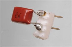
Connect it across the gate and source terminals and while it's connected, check the gate signal .Confirm that all are the same.
If you mount it on a piece of header (or similar) and put a small amount of back force on the header, it will make a good enough connection to check them without soldering.
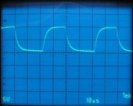
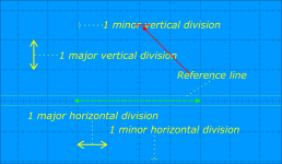
The waveform should look something like the attached waveform. Use the scope in the same settings, and DC coupling. Align the trace to the reference line before starting.
Connect it across the gate and source terminals and while it's connected, check the gate signal .Confirm that all are the same.
If you mount it on a piece of header (or similar) and put a small amount of back force on the header, it will make a good enough connection to check them without soldering.
The waveform should look something like the attached waveform. Use the scope in the same settings, and DC coupling. Align the trace to the reference line before starting.
Attachments
if we're talking about the input drivers, which legs would the gate and source be? On the datasheet I see emitter, collector, and base. Sorry for any confusion. If you want me to test the supply transistors I will have to solder them to the board
Last edited:
i wanted to make sure i'm placing this cap in the proper location before I apply power to the amp. Then i'll check the waveform of the gate pad

i get this on the 4th-6th gate pad of each group of PS FETs. Pads 1-3 of each group have a very miniscule scribble wave, almost flatline

You need to set the scope to 10uS/div and 5v/div and DC coupling and confirm that the trace deflects up approximately 2.5 major divisions when touched to the B+ terminal of the amp.
What do you get on the scope when touching the probe to the output terminals of the PS driver IC?
What do you get on the scope when touching the probe to the output terminals of the PS driver IC?
same as in post 137. Scope set up properly, I'm not sure what "2.5 major divisions" is but 10us/5v along with 1x on scope and probe are good and trace is set above 0 ref line. I get the same measurement on the scope and the PS driver IC's for those PS Fets locations give me the same result also.
.png")
- Home
- General Interest
- Car Audio
- XXV Sampson power up issues