I have a pro Roland 24 bit XLR soundcard and Dayton microphone with unique calibration file
Measure each driver separately. Be careful to not blow the tweeter out. Measure both woofer and tweeter from a certain distance, for example one meter. Measure the woofer near field ~1 cm. Try to keep the speaker as far as possible from reflecting surfaces, so you can use time-gating. Merge the near and far field response of the woofer together. Measure the impedance of drivers inside the box and import everything into XSim and you will have reliable results.
Might be a bit late to the party here but I follow Mr Waslos approach set out here...
https://www.diyaudio.com/community/threads/xsim-free-crossover-designer.259865/page-20#post-5260072
https://www.diyaudio.com/community/threads/xsim-free-crossover-designer.259865/page-20#post-5260072
Actually looking at phase this is good to do first, again I follow Mr Waslos advice here...
https://www.diyaudio.com/community/threads/xsim-free-crossover-designer.259865/page-32#post-5823284
https://www.diyaudio.com/community/threads/xsim-free-crossover-designer.259865/page-32#post-5823284
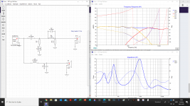
Is this the right way to do it?
Impedance files are measured on the separate drivers in the cabinet. I use Dats V3.
FRD files are traced from Seas (but i will start with my own FRD via ARTA).
Impulse response are measured with ARTA in order to set delay.
I doesnt use capasitor for protection of the tweeter when i measure. Is that a risc?
I also need more knowlegde of phase, phase tracking etc.
Looks promising!
Low impedance with high frequencies usually increases distortion from the amp, maybe you cold look at trying to increase the impedance a bit on the HP-filter to ease the load on the amp?
Another thing worth exploring IMO is impedance correction of the woofer (upper resonance with BR as you have here). Compare FR at LF of the raw driver with FR with the XO. You usually bump the FR close to resonance with a large coil.
Also compare group delay, that is where the main benefit is IMO. Use a series RLC parallel to the woofer until the impedance is basically flat in the upper resonance. Large inductor is needed, but it can be relatively cheap because DCR is not critical.
Impedance: maybe look at increasing the value of R3 to maybe 10ohm, and then re-adjust the HP values to get the same response, and impedance should be higher. I use R3=15ohm on a DXT tweeter, it's a compromise with what happens at tweeter resonance frequency. I think you are burning a large portion of the HF power in that R3 resistor.
For impedance correction, here is an example: http://www.troelsgravesen.dk/ATS-4.htm
You can also 'hold' the frequency curve with woofer coil shorted, and then put the coil back to 'normal' and compare the FR response.
There is a group delay graph in Xsim that you can open up and compare too with the hold-function if I remember correctly. Minimal group delay is good for tight bass, I also think the GD curve should be as smooth as possible, not like a roller-coaster. I avoid BR because of this, I'm a bit sensitive you might say..
Maybe better if you start a separate thread for stuff related to your speaker, and not to Xsim?
That is, a while ago I faced the same issue and it was the damn comma as decimal separatorDo your regional settings include a comma where others would use a dot?
- Home
- Design & Build
- Software Tools
- XSim free crossover designer