where is that comma?That is, a while ago I faced the same issue and it was the damn comma as decimal separator
You are faced with two options. One is to change your regional settings in windows.
However instead, first try looking at the data file in notepad. Look for commas.
Post a screenshot if uncertain.
However instead, first try looking at the data file in notepad. Look for commas.
Post a screenshot if uncertain.
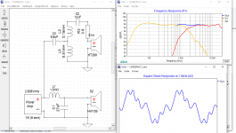
Have you tried getting square waves at your microphone? As square waves go it's not bad, but let's not forget what this is supposed to be showing. Phase.. or more importantly group delay.
Of course not, just playing with Xsim functions. Some of wich I still do not realize how to use and for what purpose. As for example applying delay to the signal generator.Have you tried getting square waves at your microphone?
I just meant do you have a point of reference. In any case I'd suggest not worrying too much about square waves. (Though I'm impressed the capability has been implemented.)
If I were to suggest a use for the generator delay, one would be to wind back phase wrapping caused by measurement delay, so that you could see it better.
If I were to suggest a use for the generator delay, one would be to wind back phase wrapping caused by measurement delay, so that you could see it better.
Thank You, very informative.If I were to suggest a use for the generator delay, one would be to wind back phase wrapping caused by measurement delay, so that you could see it better.
When i measure a MTM.
Do i measure the woofers together and also make them as one driver in Xsim?
And what is the optimal mic placement and distance?

Do i measure the woofers together and also make them as one driver in Xsim?
And what is the optimal mic placement and distance?
You can do it with microphone placed exactly in the mid point (height) between the woofers, but the distance to drivers will not be correct compared with the tweeter if you measure the tweeter in the same position/distance. You will also be slightly off-axis from both woofers, so response is not the same as perfect on axis. Better to measure them separately, more work but maybe easier to avoid mistakes. Is that Vifa C17 and DXT tweeter? In a Dali cabinet possibly?
Thx
Yes. DXT in a original Dali 104 (C17WG) enclosure with some cabinet modifications inside. Sounds fantastic.
https://www.hifisentralen.no/forume...s-dxt-oppgradering-til-glede-for-alle.103847/
https://www.hifisentralen.no/forume...bilee-modifisert-med-seas-dxt-diskant.103210/


Yes. DXT in a original Dali 104 (C17WG) enclosure with some cabinet modifications inside. Sounds fantastic.
https://www.hifisentralen.no/forume...s-dxt-oppgradering-til-glede-for-alle.103847/
https://www.hifisentralen.no/forume...bilee-modifisert-med-seas-dxt-diskant.103210/
I had a pair of the 104's too, thinking I would make another Troels C17 variant, but I was disappointed to find they had the (WG?) woofers with small magnets, not the WH. Measured Q was too high for my taste, and I did not like the bass much. I added a bucking magnet (improved Qes a bit) to one of them and use it in my DIY center channel though. I like the midrange from the C17's.
Not sure how you have damped the cabinet, but check the impedance curve of the upper woofer, you will have a standing wave around 130Hz or so, showing as a small bump in the impedance curve. Try to minimize this by adding extra wool or similar in the bottom of the cabinet. The standing wave makes bass sound 'muddy'.
I use the DXT tweeter in my Troels PMS inspired stereo speakers too. I think you can improve FR a little if you mount them flush and fill the gap around them. Looked like they were not recessed fully in your link?
My two cents worth - I feel that the resolution of your frequency response graph is too low for the purposes of assessing the performance of your crossover design.
I prefer to change the vertical axis to 5db increments.
Above 1khz I'd be trying for +/- 3db, or better.
Good luck.
I prefer to change the vertical axis to 5db increments.
Above 1khz I'd be trying for +/- 3db, or better.
Good luck.
The download link (for XSim) on page 1 of this thread appears to be broken.
Can anyone show me where to download bwaslo's latest version?
Also is there a "XSim Guide for Dummies" anywhere?
Can anyone show me where to download bwaslo's latest version?
Also is there a "XSim Guide for Dummies" anywhere?
Hi
I am playing around with Xsim, trying learn how to use it.
I am using "factory" FRD and ZMA files I have downloaded from Parts Express, etc.
Opened a new project, imported my Frd and Zma for both drivers (2 way design).
Can add circuits, etc. but can't see the curves on the graphs (SPL and IMP).
I can see the drivers (without filters) on the SPL graph, but can't see the System curve, or the Drivers in the system.
I've definitely clicked on them in the graph options, but nothing appears.
What am I doing wrong?🤢
Attachments
The curves are there, but they are way up at 170dB.
There is something wrong with the data in your files.
I would download the frd and zma files again, as something seems corrupted.
I used my own frd and zma files in your example, and it looks all ok. So, definitely something wrong with your files.
There is something wrong with the data in your files.
I would download the frd and zma files again, as something seems corrupted.
I used my own frd and zma files in your example, and it looks all ok. So, definitely something wrong with your files.

That's right. You have changed the values of sensitivity and delay. These are relative so it is reasonable to change the delay amount for factory data but sensitivity would stay at zero unless you have a reason to change it.

That's awesome.That's right. You have changed the values of sensitivity and delay. These are relative so it is reasonable to change the delay amount for factory data but sensitivity would stay at zero unless you have a reason to change it.
View attachment 1049912
Thanks guys. 👍
- Home
- Design & Build
- Software Tools
- XSim free crossover designer