Hi jReave,
Would you mind taking a look at this Xo attempt. Modified a few elements that you had mentioned. But if I'm looking at phase correctly, then it still is off in the Xo region. I have tried just about everything to no avail. Drivers appear to be in time but not where they need to be. Help!🙂I've attached modified zip.
Thanks Again,
Rich
Attachments
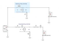
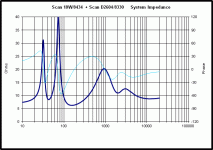
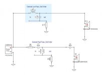
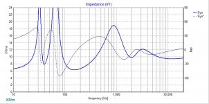
montana1 -- right-click on your highpass circuitblock, change it to discrete components. Then tweak the L and C to get the flattest response and the best phase tracking (show both S1 and S2 in the Frequency Response plot, with phase displayed for each). About 10uF and 0.22mH look better to me.
Last edited:
Hi Rich,
Just in case you didn't know, bwaslo is the designer of XSim so definitely pay attention to what he tells you.
Many, many thanks Bill for this amazing program. Fabulous versatility although for simulations without measurements, I still prefer PCD for its target slopes, power and off-axis responses and driver position data. In the case of this simulation, I wouldn't have known what the correct delay was for the woofer without working 1st in PCD and then importing the same files and xo values into XSim. Xsim required about 6mm more offset for the phase to line up the same.
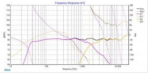
Rich, you are on the right track. Your basic topology has got things to the fine tuning stage and this time you have a lot fewer components than your 1st time around. Right now you are basically working with a 5 piece puzzle where all the values may need to be changed to get both the FR and the phase to work right. It's not a small mental challenge. Keep working at it. I can easily spend hours working on these things.
Make sure you understand how each component affects the FR and the phase and then a lot of it is just trial and error. For eg, reducing C1 to 6.8uF will give you correct phase alignment but then your FR is off. Try to get both right but in the end if you have to, give the FR a higher priority if the phase is close enough.
But in the fine tuning stage, a little secret is the added resistors in the shunt leg of either the woofer or tweeter circuit or both. They work well moving phase around. They don't need to be large either. And resistors cost peanuts. C3 on the tweeter is good at that too. Also btw, C3 usually has a larger value than C1 in a 3rd order xo.
Forgot to add that your tweeter level looks too low, at least for a starting point for voicing. It was better before at about 5ohm I think.
Just in case you didn't know, bwaslo is the designer of XSim so definitely pay attention to what he tells you.
Many, many thanks Bill for this amazing program. Fabulous versatility although for simulations without measurements, I still prefer PCD for its target slopes, power and off-axis responses and driver position data. In the case of this simulation, I wouldn't have known what the correct delay was for the woofer without working 1st in PCD and then importing the same files and xo values into XSim. Xsim required about 6mm more offset for the phase to line up the same.
Rich, you are on the right track. Your basic topology has got things to the fine tuning stage and this time you have a lot fewer components than your 1st time around. Right now you are basically working with a 5 piece puzzle where all the values may need to be changed to get both the FR and the phase to work right. It's not a small mental challenge. Keep working at it. I can easily spend hours working on these things.
Make sure you understand how each component affects the FR and the phase and then a lot of it is just trial and error. For eg, reducing C1 to 6.8uF will give you correct phase alignment but then your FR is off. Try to get both right but in the end if you have to, give the FR a higher priority if the phase is close enough.
But in the fine tuning stage, a little secret is the added resistors in the shunt leg of either the woofer or tweeter circuit or both. They work well moving phase around. They don't need to be large either. And resistors cost peanuts. C3 on the tweeter is good at that too. Also btw, C3 usually has a larger value than C1 in a 3rd order xo.
Forgot to add that your tweeter level looks too low, at least for a starting point for voicing. It was better before at about 5ohm I think.
Last edited:
Thanks for the input guys! I will work in the pointers you both suggested and see what I come up with. jReave, I have trip planned to California for about 10 days so if you don't here from me you will know why. I'll continue the chase when I return.🙂
Best Regards,
Rich
Best Regards,
Rich
Don't forget Bill is also the author of OmniMic, a spreadsheet free way to get blended response curves. The speed with which you can go from 2 drivers and a cabinet to working speaker with OmniMic, DATS and XSin is unreal. XSin is the paid version with audible responses that go "ooooh yeah baby, feels gooooooooood" when you get the FR and phase aligned perfectly. Oh, no, wait, that's me making those noises! 🙂
Best,
Erik
Best,
Erik
I wouldn't have known what the correct delay was for the woofer without working 1st in PCD and then importing the same files and xo values into XSim.
If you can do measurements, the best approach is to put the drivers in the box or baffle and do the magic 3-step:
- Measure the tweeter's response (with phase)
- Measure the woofer's response (with phase)
- Measure the response with both playing together
- Import the tweeter and woofer response into two drivers in Xsim, connected in parallel.
- Look at the frequency response window, and in its Curves menu, use Get File to load the 3rd measured response from above.
- Adjust the delay of the woofer relative to the tweeter until the both-drivers curve from Get File matches Xsim's simulation of the same.
- Leave the delays there and put in your crossover components to get the shape you want.
That will of course only work for the response looking toward the mic position you measured from. For off-axis, you would have to measure from other positions and do a similar process. (Tip: you could have several identical sets of drivers in your Xsim model, but with different off-axis FRD response files and delay adjustments in them, and only connect both terminals to the ones from the desired angle each time. Non-fully-connected drivers or other components in Xsim don't do anything, so you can leave them sitting there).
---
XSim was going to (maybe someday it still will) be able to import off -axis measurement file arrays to be able to simulate polar responses also dependent on driver placements, but that requires having files with all that data. I was working with Parts Express for them to provide all that data on their drivers, but that required a lot of pushing from me (as well as more programming) as they are busy it wasn't their top priority. There were also issues with PE not wanting to post measurements of other manufacturer's drivers that they sell (to avoid responsibilities and conflicts when things sometimes don't match), so I'd have to get those manufacturers on board, too.... too much schmoozing involved for a lowly engineer like me to take on.
For woofers, you could predict a lot of the off-axis from the diameters, but not really so much for tweeters or waveguides.
Thanks for the nice comments, Eriksqures and JReave 🙂
Baronski of Boise,
This has been a very interesting journey and its not over yet. Like I said several post back; I feel like calling this build 'In Over My Head (IOMH). Thanks goes to jReave and others for sharing their expertise. I can't imagine what things would have turned out like if I would have elected to go at this solo. Maybe a .5% chance of getting it where I could stand it through one song.🙂 Glad others are following along!
This has been a very interesting journey and its not over yet. Like I said several post back; I feel like calling this build 'In Over My Head (IOMH). Thanks goes to jReave and others for sharing their expertise. I can't imagine what things would have turned out like if I would have elected to go at this solo. Maybe a .5% chance of getting it where I could stand it through one song.🙂 Glad others are following along!
Thanks guys,
I'm starting to gather a better understanding of a few programs. As things progress, I know my tool chess will need to be expanded. But, anything you guys feel would be helpful in this build please don't hesitate to post. I'm all ears as the saying goes.🙂 Right now I'm at the fine tuning point within Xsim. I'm trying to get FR and phase matching to play nicely. Its amazing the ripple effect changing one component value has. This probably will take some time, but I will post another Xo attempt to look at when I refine things just a bit.
Best,
Rich
Well,
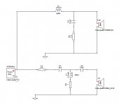
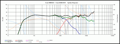
Here it is as promised. Things are starting to look better (at least to my untrained eyes).🙂 Let me know where more fine tuning is required. Maybe the blind dog will find a bone after all.😀
Here it is as promised. Things are starting to look better (at least to my untrained eyes).🙂 Let me know where more fine tuning is required. Maybe the blind dog will find a bone after all.😀
Attachments
montana,
That's a really nice looking result, especially with such simple circuits. I think it's going to be way too bright and dry sounding however, and attract more canines than you can feed. 🙂
I'd point the curve downwards somewhat, and deal with that tweeter resonance. at 20kHz or so.
It's a very nice looking set of results for a simple design.
Best,
Erik
Nicely done Rich. And that didn't take too much time at all.
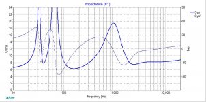
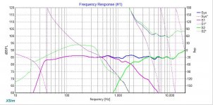
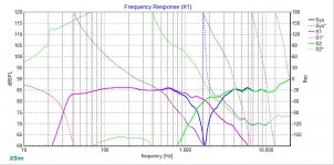
So now I'll just attach what I came up with. Compare against your's. A very slight difference. Reverse null is included as well as the power response in green.
Hope you enjoy California. If you have time before you go, I have 1 more little exercise for you to try. Let me know.
So now I'll just attach what I came up with. Compare against your's. A very slight difference. Reverse null is included as well as the power response in green.
Hope you enjoy California. If you have time before you go, I have 1 more little exercise for you to try. Let me know.
Attachments
Thanks jReave,
So the blind dog did find a bone after all!😀 It's nice to see I was on the same page as you. I like that your design has a deeper null then mine. That's a sign of excellent phase correct? Yes, I should be able to fit one more exercise in before leaving out early Thursday morning.🙂
Best Regards,
Rich
[/ and attract more canines than you can feed. QUOTE]
Erik, Its a good thing you specified canines because there is no dogs where I live just wolves and coyotes. Should we worry about them?😀
Thanks for your input. Really appreciate it. I'm sure jReave will have me address that at some point. He mentioned several posts back to leave the level up for the tweeter and we would adjust during voicing.
Best Regards,
Rich
I don't disagree that an in-room response will have a downward tilting slope but once again I have to say that that is not what we are modeling here: this is a quasi-anechoic model and as such should attempt to target a flat response. Go ahead and look at the designs by Zaph or Carmody or Bagby or Troels etc, etc and you will find that the vast majority are modeled with a flat FR. Now once you get it set up in-room, room and boundary gain will increase the perceived LF response and the diminishing off-axis response of the tweeter starting above about 5-6kHz will diminish the perceived HF response and thus a downward tilting in-room FR. Then you can adjust some levels based on your personal preferences.
Rich, compared to my sim I thought perhaps that your woofer response could come down just a touch to bring that 600Hz peak down a little more and that perhaps your tweeter could be padded a little more too. I changed my tweeter padding at the last minute from 5ohm to 4.5ohm but I'm changing my mind again and think that 5ohm is better place to start. If anything might be off in my model, look at the FR between about 3kHz and 6kHz which is where the on-axis FR and the off-axis FR are at about the same level whereas above and below that they are not. Perceptually, this may make that frequency range sound louder and this is in that area that people typically label as the ear's most sensitive. So dropping it a little may indeed be called for.
The other thing I want to look at is the bass levels. If I recall correctly you were wondering about how much baffle step loss you were likely to see. Now that the 1st bone has been found so to speak, now is probably a good time to ask you about your room size (small, medium or large; open concept vs completely self-enclosed?) and about speaker placement (distance to back and side walls?). These will inform your box tuning as well as bsc. Let me know and I figure I'll get you to do another sim but this time with only 3 or 4dB of bsc.
Thanks jReave,
I will look at adjusting the two areas you mentioned. As for room size, It is a small self enclosed office room 10' by 15' with 8' high ceiling . Speakers will be placed approximately 5' from side walls and set 18" away from wall unless you advise otherwise. I don't know if type of music matters, but if it does then my preference is classic rock and blues. So, if there is a bias to midrange and lower treble; I won't mind.🙂
Best,
Rich
To my eye, the little hill right at the xo still looks high. But considering the off-axis response in the exact same spot is also lower, it may be fine. We can play with the sim in this kind of micro detail all we want and it's good to know what values you have to use to change things up, but really this is the kind of thing to try by ear and see if you can hear any difference and if so, which one you like best and that's for just a little down the road.
In a room that size you are actually going to get a fair amount of room gain in the LF so I would look at how your room gain and your vented tuning model together. Start off by looking at the room pressurization module in Bagby's separate Diffraction program and I'll carry on with this tomorrow. Most people fail to look at this when going vented and it's a common cause of boomy, bloated bass.
In a room that size you are actually going to get a fair amount of room gain in the LF so I would look at how your room gain and your vented tuning model together. Start off by looking at the room pressurization module in Bagby's separate Diffraction program and I'll carry on with this tomorrow. Most people fail to look at this when going vented and it's a common cause of boomy, bloated bass.
- Status
- Not open for further replies.
- Home
- Loudspeakers
- Multi-Way
- Xsim Critique Part 2