Right then, let's look at the graphs below:
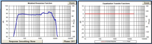
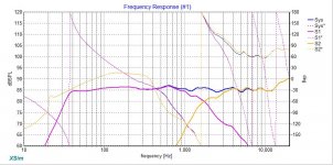
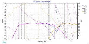
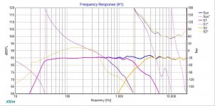
1) simmed room gain with longest dimension of 15', 50% estimated loss
2) simmed 18W in 42L Fb= 40Hz
3) 18W plus baffle diffraction
4) 18W plus baffle diffraction plus room gain
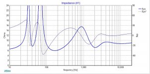
What we are looking for here is to avoid any sharp peaking in the bass response and that's what we are getting at about 40Hz (don't forget the xo will be pulling everything north of 200Hz down to about 85dB). So what you want to do is by trial and error re-do Vb and Fb until you flatten that peaking out of the response.
Have look here at the Bagby School of Speaker Design for some more info:
My take on Flat Response and when I might not - Techtalk Speaker Building, Audio, Video Discussion Forum
https://app.box.com/s/3oybwh0qtil8qj9knd2l
Once again, response Modeler is your friend here.
First use Bagby's Diffraction Simulator to get your room gain curve. Save the frd file.
Then import zaph's raw FR back into RM and splice in your chosen box tuning.
Then set up the woofer's baffle response and combine with the spliced response.
Finally, import the room gain.
Alter the box size and/or tuning until you get rid of the peaking (you'll have to clear the baffle and room files before splicing and then combine them back in for each attempt).
Let me know if I haven't made that clear enough to follow.
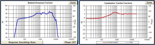
1) simmed room gain with longest dimension of 15', 50% estimated loss
2) simmed 18W in 42L Fb= 40Hz
3) 18W plus baffle diffraction
4) 18W plus baffle diffraction plus room gain
What we are looking for here is to avoid any sharp peaking in the bass response and that's what we are getting at about 40Hz (don't forget the xo will be pulling everything north of 200Hz down to about 85dB). So what you want to do is by trial and error re-do Vb and Fb until you flatten that peaking out of the response.
Have look here at the Bagby School of Speaker Design for some more info:
My take on Flat Response and when I might not - Techtalk Speaker Building, Audio, Video Discussion Forum
https://app.box.com/s/3oybwh0qtil8qj9knd2l
Once again, response Modeler is your friend here.
First use Bagby's Diffraction Simulator to get your room gain curve. Save the frd file.
Then import zaph's raw FR back into RM and splice in your chosen box tuning.
Then set up the woofer's baffle response and combine with the spliced response.
Finally, import the room gain.
Alter the box size and/or tuning until you get rid of the peaking (you'll have to clear the baffle and room files before splicing and then combine them back in for each attempt).
Let me know if I haven't made that clear enough to follow.
Attachments

Thanks jReave,
I just downloaded Bagby's Diffraction and Boundary Simulator and will begin working on getting that peaking bass response flattened. I may not complete the process before leaving for California tomorrow morning but will pursue the chase upon returning. Also, I would like to spend some time reading the articles you mentioned before jumping right in. BTW, your explanation is very clear. Really appreciate your assistance on this project!
Best Regards,
Rich
Hi jReave,
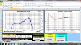
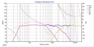
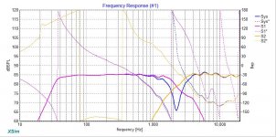
I had a little time to work through RM and try to find optimum Vab and Fb. Funny that what I came up with is Vab= 24 liters and Fb= 44 hz. This after expanding box to 42 liters. Not the end of the world. I will need to block off a few holes in last brace unless you have another idea. I guess we will cross that bridge later. Here is screenshot with room gain, box splice, and diffraction.
Best,
Rich
Attachments


Hi jReave,
If the next step is to take new frd. file and extract minphase and import back into Xsim for additional fine tuning then I have a few files to look at. I'll keep track of posts on my trip in case you reply.🙂
Thanks a Million!
Rich
If the next step is to take new frd. file and extract minphase and import back into Xsim for additional fine tuning then I have a few files to look at. I'll keep track of posts on my trip in case you reply.🙂
Thanks a Million!
Rich
Attachments
There is a tiny bit of discrepancy between our models, perhaps due to the value of our series resistance which should be equal to your woofer inductor's resistance (I see you've used .35ohm) and then I add .2ohm for the approximate resistance of your speaker wire, etc., maybe more for longer runs of wire.
But again don't sweat the finer details of these simulations too, too much because in the end, you'll want to put the speakers into your room and listen with your ears and then make any adjustments you think are appropriate.
In terms of another xo sim, since we have only changed the response below probably 100Hz or so, there isn't actually any reason that the same xo as before won't work again here.
Looking at your xo in post #88 anyways, you've reduced your woofer inductor so I'll again comment that the 600Hz peak looks too high to me now. Probably. But it's still a good exercise for you to find different combinations of values that work together.
At this stage or even before, it's always a good idea to have a look at any other designs that might use these drivers and see how they handled them, even if different xo points may have been chosen for different reasons. Both Troels and Humble Homemade Hifi have used that tweeter and looking at them made me see that I missed having a good look at the tweeter's impedance peak which I think both of those designers chose to compensate for with LCR notch filters so I'm thinking that's probably a good idea. My oversight on that one. Now if you're asking yourself, "how do I figure that 1 out?", here's another advantage of PCD in that it will do some automatic filter calculations for you and then you can make adjustments from there. I'll post those values when you get back.
BTW, looking at that Concerto design, it occurred to me that you might want to consider something similar to that type of internal cabinet treatment behind the drivers as a way for you to reduce the Vb of your cabinet and possibly achieve an improvement in SQ at the same time. Just a thought. Probably depends on what stage you're at with the build and/or whether or not it's all glued together or not.
Yea, probably got a little carried away trying to reduce little hill at Xo point. We will continue the pursuit upon my return. It has certainly been fun and exciting project. Best, Rich
Hi jReave,
I'm back from my trip and ready to resume the design process. I wanted to take a moment and let you know where I'm at in the build process. I'm very close to completing (1) cabinet outside of the veneer work. Although, it will not be difficult to reduce box volume to 34L. I found the Concerto build very interesting but I'm a little to far into this build to change direction. I will certainly keep that design in mind for a future build🙂 The one question I have is: How much does damping material reduce net box volume? I'm using 1" close cell foam (mattress topper). I have read several articles here and other sources but am still not sure of an overall consensus. What is your views on the the subject? Again, your assistance is very much appreciated!
Best,
Rich
Hope you had a good time in California!
Again, I don't know what your cabinet design is looking like but in terms of the Concerto and what he calls a Quadratic Residue Diffuser, I wasn't thinking that you had to imitate that exactly, but that using the area behind the mid/woofer to add some wood in whatever way might work might reduce cabinet volume and improve the breakup and/or diffusion and/or absorption of some of the midrange frequencies at the same time. Another option could be to add wood so the rear starts to look something like a narrowing, inverted pyramid.
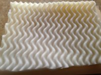
Are you sure that your mattress topper is close celled? The stuff I've seen has been the opposite. Try breathing through it, that will let you know.
While you were gone, I happened to find a design using your exact drivers which I think you should read: 18W-8434G00. He's got some different TS parameters (again) which you should probably run through to see how they work out and maybe choose an average Vb between Troel's and Zaph's.
When I design xo's for somebody else, I tend to be conservative in my choice of xo slopes and points etc when I haven't used the drivers before, but here you can see that Troel is happy with a higher xo point for the woofer than I was suggesting and that he prefers shallower slopes as well. He also has a tendency to use smaller inductors on the woofer and then to add in a series LCR notch filter in parallel in order to smooth out any remaining peaking/increase in the midrange response.
Have a look and perhaps try to see if you can find a different xo that works with our data that incorporates these ideas. Up to you of course what you want to do.
Again, I don't know what your cabinet design is looking like but in terms of the Concerto and what he calls a Quadratic Residue Diffuser, I wasn't thinking that you had to imitate that exactly, but that using the area behind the mid/woofer to add some wood in whatever way might work might reduce cabinet volume and improve the breakup and/or diffusion and/or absorption of some of the midrange frequencies at the same time. Another option could be to add wood so the rear starts to look something like a narrowing, inverted pyramid.
Are you sure that your mattress topper is close celled? The stuff I've seen has been the opposite. Try breathing through it, that will let you know.
While you were gone, I happened to find a design using your exact drivers which I think you should read: 18W-8434G00. He's got some different TS parameters (again) which you should probably run through to see how they work out and maybe choose an average Vb between Troel's and Zaph's.
When I design xo's for somebody else, I tend to be conservative in my choice of xo slopes and points etc when I haven't used the drivers before, but here you can see that Troel is happy with a higher xo point for the woofer than I was suggesting and that he prefers shallower slopes as well. He also has a tendency to use smaller inductors on the woofer and then to add in a series LCR notch filter in parallel in order to smooth out any remaining peaking/increase in the midrange response.
Have a look and perhaps try to see if you can find a different xo that works with our data that incorporates these ideas. Up to you of course what you want to do.
Thanks jReave,
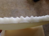
I have attached a couple photos for you to get a better idea of damping material being used. It is fairly restrictive trying to breath through it. I'm sure this will determine what percentage box volume is affected. Unfortunately, I have attached front baffle and cannot make use of your box mod suggestions, unless I walk away from this cabinet and start from scratch. But, before doing anything drastic I will wait until running through Troel's TS parameters and see what VB I arrive at. I'm confident that if arrive reducing box volume is required, then its just a matter of cutting a few inches from the bottom of cabinet (easy).🙂 I'm just kicking myself on jumping the gun on starting the build process before the design process was completed. Another learning experience, and something to share with others.
I will start running some more simulations with different crossover points and post those once I have something that looks decent.
Best Regards,
Rich
Attachments
Last edited:
I'm not sure if anyone is going to recommend using closed cell foam. I don't know what its sound absorption properties are compared with open cell and it definitely won't effectively increase Vb the way open cell does. With my sims in Unibox, I've already included covering the cabinet walls with some kind of insulation (open cell) to arrive at the proposed cabinet volumes.
In your application, a floorstanding vented 2-way, I was going to suggest open cell mattress topper or something like rigid Rockwool on your walls and then some additional light use of Polyfill behind the driver to help absorb more of the high frequencies. PE has some specially designed acoustic foams if you want to pay for them or maybe try Walmart for open cell mattress topper and pillow stuffing.
In your application, a floorstanding vented 2-way, I was going to suggest open cell mattress topper or something like rigid Rockwool on your walls and then some additional light use of Polyfill behind the driver to help absorb more of the high frequencies. PE has some specially designed acoustic foams if you want to pay for them or maybe try Walmart for open cell mattress topper and pillow stuffing.
Thanks jReave,
I will remove that item from cabinet and look for open cell foam from Wallmart or elsewhere. Already have stole a pillow from the wife for the poly material.🙂
Best Regards,
Rich
I will remove that item from cabinet and look for open cell foam from Wallmart or elsewhere. Already have stole a pillow from the wife for the poly material.🙂
Best Regards,
Rich
Hi jReave,
I have attached Xsim zip with a few screen shots for you to take a look at (if you don't mind).🙂 It looked like Troel's selected a crossover point around 2.2k so that was my target as well. I'm still trying to smooth hill around 600 hz but not having too much success. Like you said before, it may not matter in the end. Also, I tried plugging in Troel's TS parameters into Response Modeler and it made very little difference. So, I will stick with 34 L box volume and 42 hz tuning (unless you discovered something different in your simulations).🙂
Best Regards,
Rich
Attachments


I actually hadn't tried Troel's data, so it's good to know it works out about the same as Zaph. Good driver consistency.
The LCR on the tweeter is nicely effective at dropping the rising response at the highest frequencies, but again, I'm not sure that you really need it. Good to try anyways but try this - just put about a .1mH coil in series either before or after the xo and see what that does. Increase the value if necessary. Actually I just tried it and your filter looks like it works a little better here. I'm not exactly sure if you are going to be able to find a .06mH coil though. Maybe you could unwind a .1mH one though.
Here's what I'm thinking of for the woofer:
- try starting with a lower inductor value, say about 1mH
- add a capacitor and a resistor (in series) in parallel with the inductor (you had one like this in the 1st sim that you posted I think) aimed at smoothing out the rolloff around 5000Hz
- add in the shunt capacitor and resistor as you think works best
- and then add a series LCR notch in parallel to flatten the peaking that still sits in the midrange (and here's a little tip for working with notch filters - choose an effectively very high resistance to start off with as that will make the location of the notch so much easier to see. Notice I said "effective" resistance, since a very small value does this when it's in parallel and a very large value does this when it's in series)
Notches can be hard to work with at first btw. Try to think of what inductors and capacitors regularly do when you put them in either series or parallel depending on which type of notch filter you are using and how those 2 values are going to work together. There will actually be many different values that will produce notches at the same frequency but the notch will be either wider or narrower depending on what values you choose (ie. notch Q).
I mentioned before you left, I think you are going to want to use a resonance compensation filter on the tweeter. Troels uses them on that link I last gave you. To see its effectiveness (cause you may want to try and reduce some values if you can), look at the impedance response when you add the filter before any other xo components are added to the tweeter circuit.
Thanks jReave,
I will begin working on those changes this evening and see what I can achieve. Everything you mentioned seems very straightforward and easy to understand.
Best,
Rich
I will begin working on those changes this evening and see what I can achieve. Everything you mentioned seems very straightforward and easy to understand.
Best,
Rich
Hi jReave,
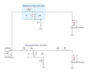
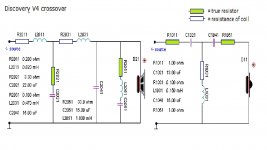
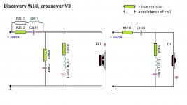
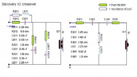
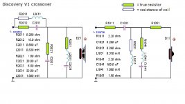
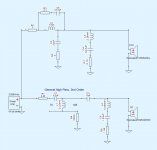
I'm trying to understand resonance compensation filters and their uses. I looked extensively at the Troel's Discovery W18 you referenced and I'm not seeing how he uses it on this tweeter. Would you mind pointing it out to me? I have attached the 4 schematics he listed.
Thanks a million!
Rich
I'm trying to understand resonance compensation filters and their uses. I looked extensively at the Troel's Discovery W18 you referenced and I'm not seeing how he uses it on this tweeter. Would you mind pointing it out to me? I have attached the 4 schematics he listed.
Thanks a million!
Rich
Attachments
Hi jReave,
I have attached a few more screen shots from my latest invention. I'm not completely sure this is what you had in mind, but its looking much smoother throughout the FR. Hopefully, I'm on the right track.🙂
Best Regards,
Rich
I have attached a few more screen shots from my latest invention. I'm not completely sure this is what you had in mind, but its looking much smoother throughout the FR. Hopefully, I'm on the right track.🙂
Best Regards,
Rich
Attachments

- Status
- Not open for further replies.
- Home
- Loudspeakers
- Multi-Way
- Xsim Critique Part 2