Hi Erik, My HF filter has this although I don't understand why.
Could you please explain what is the purpose of using a very small inductor prior to the driver?
Thank You.
Hi BoB!
First, you can always use XSim to try this out, even if you have to use the "vanilla" drivers that come with it. You could make up your crossover and then try to add this or remove it.
If the coil is not in parallel with a resistor, you can use it to tilt the tweeter response downwards. Say for instance your tweeter had a gentle rise you wanted to turn flat.
Used in parallel with a resistor, you could bump up the low-end of the tweeter.
In both cases this coil is doing more EQ duty than filtering in the normal sense. Done well and sparingly you can do this without affecting the actual filter slope/knee points.
Of course, you can argue that all filters are EQ, and all EQ's filters. I'm just using these words to try to illustrate the practical use of them. No doubt some plebe will jump in to assert my ignorant use of the words. << sigh >>
Best,
Erik
Well you have to be careful which words you choose on this forum. 🙂
I thought that might be the case.
The Heil AMT drivers are very bright and sensitive, so makes sense that ESS would add this small inductor to bring it down a bit.
I have downloaded XSim and tried to use it a little.
It is really nice for free styling in the components.
However, I have not figured out how to enter the T/S params for the drivers.
Is this "ideal" driver you speak of often the default driver without params?
Appreciate you explaining the coil.
Last edited:
jReave,
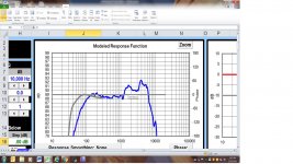
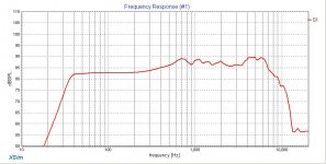
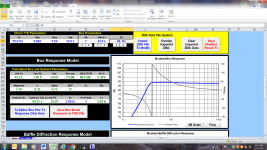
I've attached the FR frd. trace from Zaph. I also included a few more screen shots to see if I'm on the correct path. One value in baffle response model was inputted incorrectly which probably affected spl being to high. Rookie move on my part.🙂
Thanks,
Rich
I've attached the FR frd. trace from Zaph. I also included a few more screen shots to see if I'm on the correct path. One value in baffle response model was inputted incorrectly which probably affected spl being to high. Rookie move on my part.🙂
Thanks,
Rich
Attachments
BoB,
XSim doesn't do cabinet modelling I'm afraid, so it has no use for T/s parameters. XSim does do electro-acoustics. For this it needs the in-cabinet impedance and in-cabinet driver FR plots. That's it.
If you want to model a cabinet simply, WinISD will happily input all your T/s parameters. 🙂
Best,
Erik
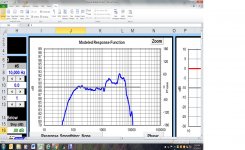
....What I want is to see what your simulated woofer FR looks like before you start working on the xo. This will be the frd file that you import into XSim. Right now it looks to me like your SPL level is too high.
So you can:
- attach that file (the frd. file extension needs to be changed to txt.) or
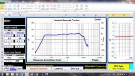
- attach an image of the FR in a graph. You could use a chart from XSim before you start on the xo or you could take a screen shot of Response Modeler's top graph (zoom to a more detailed scale), import it into MS Paint and save it as a jpeg or gif. or
- maybe there's another way I haven't thought of yet.....
One easy way would be to attach the actual Xsim file as saved (suffix would be ".dxo"). That file contains everything that gets entered into a model including responses and impedance curves. It can be opened directly with a computer running XSim.
Bill
Rich, that looks great and helps me to see that you've got it down correctly this time.
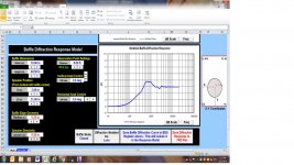
Three things to note. First, a 1/4" roundover doesn't really have much of an effect. Second, in the box modeling section, to be completely accurate you want to add in the series resistance that you are likely to use in the xo - probably about .3ohm or .4ohm - because this will slightly change your box response, albeit only to a very small extent. And third, it's also worth noting that you are getting a bit of a rising response in the 80Hz region. This isn't actually a bad thing in a small 2-way (it can give the illusion of deeper bass) but you'll want to keep an eye out that it doesn't become too large when you add in the xo, as a side effect can be an increase in SPL down near the drivers Fs.
Let me suggest that you start off in XSim again on the woofer. Try 2nd order electrical, maybe with an added resistor in the parallel leg, maybe not. Set your target SPL level at about the woofer's level at 200Hz.
Then try 3rd order electrical on the tweeter. Again, perhaps some extra resistance on the parallel leg. And that's it. Maybe the tweeter polarity needs to be flipped. See if you can find a nice combination of values that will make that topology work out. I don't think you really need anything else that you've been throwing at it.
Thanks Bill, I figured there was at least 1 other thing that I was missing!
Test .dxo file upload
Just found that the ".dxo" file type isn't allowed to be uploaded for some reason (I guess it isn't recognized by whoever set up the forum website?).
Anyway, a way to do it is to zip up the file (unless you selected otherwise, it is probably in your C:\Users\Public\XSim\designs folder).
**To zip up a file:**
Anyone wanting to open your file then in Xsim will need to go to where their copy of the zip file got downloaded to, and uzip it somewhere convenient. Double-click on the file name to open it up (or do "File Load" from inside Xsim).
(A dxo file is a human-kinda-readable format, btw, all ASCII text).
An example is attached here....
Just found that the ".dxo" file type isn't allowed to be uploaded for some reason (I guess it isn't recognized by whoever set up the forum website?).
Anyway, a way to do it is to zip up the file (unless you selected otherwise, it is probably in your C:\Users\Public\XSim\designs folder).
**To zip up a file:**
Find the .dxo file in your Windows File Explorer
Right-click on the file name, left-click on the menu "Add to...".
Change "Save as type" to "Zip archive (*.zip)".
In the left pane, select the folder you want the zip file to be saved in, Somewhere easy to find, such as your Documents folder.
Give it a recognizeable name, then click "Save"
Then attach the new zip file to your post.Right-click on the file name, left-click on the menu "Add to...".
Change "Save as type" to "Zip archive (*.zip)".
In the left pane, select the folder you want the zip file to be saved in, Somewhere easy to find, such as your Documents folder.
Give it a recognizeable name, then click "Save"
Anyone wanting to open your file then in Xsim will need to go to where their copy of the zip file got downloaded to, and uzip it somewhere convenient. Double-click on the file name to open it up (or do "File Load" from inside Xsim).
(A dxo file is a human-kinda-readable format, btw, all ASCII text).
An example is attached here....
Attachments
Last edited:
jReave Thanks,
I will get started on that and see what I get accomplished over the next couple days.
Best Regards,
Rich
I will get started on that and see what I get accomplished over the next couple days.
Best Regards,
Rich
Hi jReave,
I have put together a crossover design with the topography you suggested. Try not to laugh to hard.😀. It is a bit of a roller coaster ride through to summation point. I tried to smooth out hump around 800 hz and upward zinger at 10 khz to no avail. As always, your help smoothing this out some would be much appreciated.🙂 Attached is screen shots and zip file. Hopefully, it opens correctly.
Best Regards,
Rich
Attachments
use circuit blocks! 🙂
Try the attached file. It's full of ideas for you to learn about. 🙂 However I think your tweeter phase data is wonky. It's flat when it should be at a significant slope. So I don't trust the phase matching. Here's what I would typically expect, taken from a Tymphany Ring Radiator I'm working with right now, but it's typical relationship of flat FR with changing phase due to having no group delay through the flat FR region:

Erik
Try the attached file. It's full of ideas for you to learn about. 🙂 However I think your tweeter phase data is wonky. It's flat when it should be at a significant slope. So I don't trust the phase matching. Here's what I would typically expect, taken from a Tymphany Ring Radiator I'm working with right now, but it's typical relationship of flat FR with changing phase due to having no group delay through the flat FR region:
Erik
Attachments
Last edited:
Hi jReave,
I have put together a crossover design with the topography you suggested. Try not to laugh to hard.😀. It is a bit of a roller coaster ride through to summation point. I tried to smooth out hump around 800 hz and upward zinger at 10 khz to no avail. As always, your help smoothing this out some would be much appreciated.🙂 Attached is screen shots and zip file. Hopefully, it opens correctly.
Best Regards,
Rich
Hey Rich, fear not. One, I'm not the type of person to laugh at others. And 2, you're on the right track.
Now actually, it's not that much of a roller coaster. The bump at 800Hz you do need to pay attention to but don't worry about the rising response above 14k or 15kHz - unless you're still 16, you probably can barely even hear that high.
Two problems that I see and I've just looked at the woofer are 1, as Eric points out, it looks like the phase isn't right which probably means minimum phase on either the FR or the z or both wasn't done. But second, the bigger problem is that I think that your woofer file still isn't right. All the files that you build up to get to Xsim can get confusing when you are starting out so you need to figure out a labeling and file system that works and makes sense for you. My feeling is that you may have imported the wrong file(s).
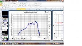
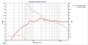
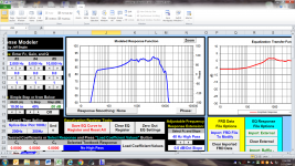
First chart below is your woofer FR from RM from your post #23 with box and baffle effects included. Simply extract minimum phase from this file and then import it into XSim. The next chart is my own results (darker blue is the unfiltered FR) which confirm that your's are indeed correct. But the 3rd chart shows your woofer FR in your latest xo sim but without any xo components added. It should be the same as the others but is not. Its level is both low and not quite the same shape. Perhaps the wrong file?
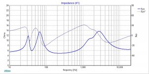
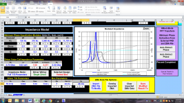
Also, I've just looked at your woofer impedance file too. The lower, box response portion is correct with a tuning at 40Hz (the low point between the nulls) but the rest of it is off. Look at the value at 10kHz for eg. - the pdf has it up above 20ohm but if you look at your woofer z curve, it's only at about 7 or 8ohm at 10kHz. That translates to incorrect component values in the xo despite the fact that the curve may look good. It does look to me as though you have extracted the minimum phase on it though.

Skip the solo resistor in parallel on the woofer too. It's not necessary.
So, process problems still. Perhaps write out the necessary steps to create your files and then follow them step by step until you get more used to it. Post the XSim file again once you input your files but before you do any xo work if you'd like me to double check them. That worked well this time.
Attachments

Thanks jReave,
I forgot to mention that I expanded cab to 42 liters net (the entire box volume utilized). Then went back though Response Modeler with those numbers. It changed the curve quite a bit. But, for a sanity check; I will revisit the entire process once again. Troels has his Cost No Object build (CNO). I think mine will be called ' In Over My Head' (IOMH!)😀
Best Regards,
Rich
Thanks Erik,
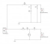
Appreciate sharing that schematic. That looks tons better then my lowly attempt. I will also review the tweeter file. Something may have been done incorrectly in the process.
Best Regards,
Rich
Appreciate sharing that schematic. That looks tons better then my lowly attempt. I will also review the tweeter file. Something may have been done incorrectly in the process.
Best Regards,
Rich
Hi jReave,
Thanks for being so patient with me. Here is the zip file with no crossover work performed. Could you check it out? Also, I went back through a modeled woofer again. I had by mistake used the incorrect trace. Before you mentioned using Zaph; I had done one from Troels website. I should have saved it somewhere else to avoid confusion. Another rookie move, but I will learn. File management is very important I see. I have also included screen shoots from Response Modeler once again because of the box volume increase to 42 liters.
Best Regards,
Rich
Attachments
jReave,
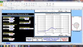
I might have incorrectly set observation point in baffle diffraction model to low. The tutorial from Paul Carmody has it set to 8 feet. Is that the correct figure?. In the screenshot from my prior post it was set to .5 feet. I'm attaching another zip file with correction made to baffle step and screenshot from Response Modeler.
Thanks a Million,
Rich
Attachments
Hi Rich,
Here's how it looks to me at this point: you've got the steps down right but now you have to just make sure that you get the details right in each step. Here's how your files look compared to mine.
Woofer FR:

Excellent. Pretty much bang on. Phase is probably a tiny bit different because I used a different program to extract it.
Woofer Z:
Still off but I didn't re-post the graph because it's just the same problem as last time - I'm pretty sure you have traced Zaph's Z measurement incorrectly. Or to be more precise, I suspect you have traced it correctly but the vertical scale you used was incorrect. Don't feel bad, this is something I did about 4 times in a row last week. So try to be precise in your setting of the scale limiting lines, make sure you input the correct values for those lines and for the impedance make sure that you have chosen the right linear or logarithmic scale. With both the quick tracer and SPLTrace programs, there are registers down in the bottom left corner that correspond to the coordinates of your curser. Primarily with impedance, I try to always double check the accuracy of my ohm scale by moving the curser to different vertical points and making sure that the values are indeed correct.
Tweeter FR: (mine is green)


First, there's a little discrepancy up at the top end. Again I suspect a scale mistake when tracing. And 2nd, our baffle diffractions are not the same. Maybe I've got some of my data wrong, but I certainly end up with more peaks and valleys that you do.
Two small details: Effective piston diameter is usually measured from mid surround to mid surround. I got 5.5" for your woofer and the tweeter would be 1". Distance at 8' is correct - there is no loss at the upper frequencies so it should be at 0dB. Maximum loss should be -6dB.
Tweeter Z: (mine is black)

Just off by tiny amounts so again just a scale setting error in tracing. Perhaps try double checking visually against the original graphs after you've done your tracing.
There's a learning curve here so don't be too perturbed. And mistakes are in fact very effective learning tools for getting it right in the end. Next time should be the charm. 🙂
Here's how it looks to me at this point: you've got the steps down right but now you have to just make sure that you get the details right in each step. Here's how your files look compared to mine.
Woofer FR:
Excellent. Pretty much bang on. Phase is probably a tiny bit different because I used a different program to extract it.
Woofer Z:
Still off but I didn't re-post the graph because it's just the same problem as last time - I'm pretty sure you have traced Zaph's Z measurement incorrectly. Or to be more precise, I suspect you have traced it correctly but the vertical scale you used was incorrect. Don't feel bad, this is something I did about 4 times in a row last week. So try to be precise in your setting of the scale limiting lines, make sure you input the correct values for those lines and for the impedance make sure that you have chosen the right linear or logarithmic scale. With both the quick tracer and SPLTrace programs, there are registers down in the bottom left corner that correspond to the coordinates of your curser. Primarily with impedance, I try to always double check the accuracy of my ohm scale by moving the curser to different vertical points and making sure that the values are indeed correct.
Tweeter FR: (mine is green)
First, there's a little discrepancy up at the top end. Again I suspect a scale mistake when tracing. And 2nd, our baffle diffractions are not the same. Maybe I've got some of my data wrong, but I certainly end up with more peaks and valleys that you do.
Two small details: Effective piston diameter is usually measured from mid surround to mid surround. I got 5.5" for your woofer and the tweeter would be 1". Distance at 8' is correct - there is no loss at the upper frequencies so it should be at 0dB. Maximum loss should be -6dB.
Tweeter Z: (mine is black)
Just off by tiny amounts so again just a scale setting error in tracing. Perhaps try double checking visually against the original graphs after you've done your tracing.
There's a learning curve here so don't be too perturbed. And mistakes are in fact very effective learning tools for getting it right in the end. Next time should be the charm. 🙂
Much Thanks jReave!
It appears my trace efforts need more attention. There is certainly a learning curve to each of these programs. But, to do this right, accuracy is paramount. I will go back and retrace everything except woofer FR since you thought it to be bang on. Once I have those done, I will get back to you with an adjusted Xsim with accurate info. BTW, I'm having to much fun to be getting perturbed or frustrated in anyway. 🙂
Best Regards,
Rich
- Status
- Not open for further replies.
- Home
- Loudspeakers
- Multi-Way
- Xsim Critique Part 2