Hi jReave,
I'm using SplTrace. I tried to use Spl copy and could not get it to work correctly. I'm going to stick with SplTrace unless you recommend something better.
Best Regards,
Rich
I'm using SplTrace. I tried to use Spl copy and could not get it to work correctly. I'm going to stick with SplTrace unless you recommend something better.
Best Regards,
Rich
Hi Rich,
Sorry to tell you but all 4 files are just a little bit out.
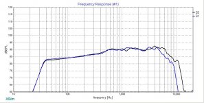
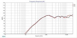
The first 2 graphs below are the FR comparisons for the woofer and tweeter (my files are all in black). In both cases they deviate up at the higher frequencies. This time I went into the quick trace program to look for the reason and it looks like what you have done is set the scale line at 10kHz but called it 20kHz. Or perhaps at 20kHz and called it 30kHz. That's a simple fix.
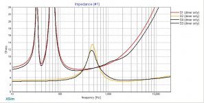
The 3rd graph shows the impedance comparisons. Just so we know that we are comparing apples to apples, I am using Zaph's impedance zooms for the drivers (actually his data for everything). In the case of the tweeter, he measured 2 samples - here I've used sample 1.
It is unclear to me why our curves are slightly different. I re-did my files just to be sure, visually double checked them at significant points and am confident they are correct. So I'm not sure what to tell you about the tweeter other than try again.
The woofer file on the other hand has more chance for error because you have to manipulate it. On the left side of the curve, we diverge because you have still included the series resistance (.8ohm?) in the sim. You want to do this to see how it will affect the simmed box FR, but when working with the impedance you can leave it out since you will be adding this back into the woofer circuit when you put the inductor and its resistance into your xo sims. (If you were measuring the in-box impedance, it wouldn't be there in other words) The right portion is a matter of again accurate tracing and then good manipulation of the curve.
Maybe this will help this time: I've included my 4 files for you to compare against. You'll need to change the extensions back to .frd and .zma.
Hope that helps. 🙂
Sorry to tell you but all 4 files are just a little bit out.
The first 2 graphs below are the FR comparisons for the woofer and tweeter (my files are all in black). In both cases they deviate up at the higher frequencies. This time I went into the quick trace program to look for the reason and it looks like what you have done is set the scale line at 10kHz but called it 20kHz. Or perhaps at 20kHz and called it 30kHz. That's a simple fix.
The 3rd graph shows the impedance comparisons. Just so we know that we are comparing apples to apples, I am using Zaph's impedance zooms for the drivers (actually his data for everything). In the case of the tweeter, he measured 2 samples - here I've used sample 1.
It is unclear to me why our curves are slightly different. I re-did my files just to be sure, visually double checked them at significant points and am confident they are correct. So I'm not sure what to tell you about the tweeter other than try again.
The woofer file on the other hand has more chance for error because you have to manipulate it. On the left side of the curve, we diverge because you have still included the series resistance (.8ohm?) in the sim. You want to do this to see how it will affect the simmed box FR, but when working with the impedance you can leave it out since you will be adding this back into the woofer circuit when you put the inductor and its resistance into your xo sims. (If you were measuring the in-box impedance, it wouldn't be there in other words) The right portion is a matter of again accurate tracing and then good manipulation of the curve.
Maybe this will help this time: I've included my 4 files for you to compare against. You'll need to change the extensions back to .frd and .zma.
Hope that helps. 🙂
Attachments
-
 wfr comparison v2.jpg88.9 KB · Views: 135
 -
 twtr comparison v2.jpg88.5 KB · Views: 136
 -
 Z comparison v2.jpg94.6 KB · Views: 134
 -
18W8434 VB 42L 40Hz.txt31.7 KB · Views: 67
-
wfr Z + phase modified VB 42L Fb 40Hz by Zaph.txt13.1 KB · Views: 66
-
RM twtr on 10x40.5bfl @37 r=0.txt13.6 KB · Views: 60
-
raw Z + phase by zaph sample 1.txt24.4 KB · Views: 65
Hi jReave,
I'm using SplTrace. I tried to use Spl copy and could not get it to work correctly. I'm going to stick with SplTrace unless you recommend something better.
Best Regards,
Rich
Yes, try this one: New automatic graph tracing program.
It doesn't work for all graphs, but most of the time it is far easier, quicker and accurate.
Thanks jReave,
I will download this program and begin working files over again. Darn, I thought everything would be correct. My only concern was frequency coordinates did not match perfect in relation to Zaph's chart. Even though, I had set the alignment values as shown on Zaph's chart. I believe on one in particular, it start off correctly at 10 hz but by the end of the trace it showed 5,300 hz when it should have been approximately 6,700 to match Zaph chart (woofer impedance graph). Anyway, I will leave trying to figure out that program for now. Maybe the 4th time is the charm!
Best Regards,
Rich
Hi jReave,
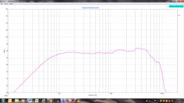
I have attached a few screenshots for you to analyze before I proceed on with FP Graph Tracer (if you don't mind).🙂 Seems it is more user friendly and accurate program than SplTrace. Just a couple questions in the trace settings.
1.)Do I need to check the logarithmic box for the y axis? Screenshot from authors web page had it unchecked.
2.) It appears program is trying to also trace a partial amount of the impedance line. How do I eliminate that and only allow trace of fr (in this case)?
3.) Could you also double check that I have boundaries set correctly and all is good to go.
Thanks a Million!
Rich
Attachments
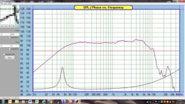
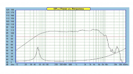
Isn't that a much nicer program?
1) Not for Zaph's graphs. His scale is linear (1, 2, 3, 4, 5, etc). Other graphs are base-2 (0, 4, 8, 16, 32, etc.). Still others are on the odd occasion base-10 and for that you'll have to go back to SPLTrace.
2) Yes, the program sort of reads the heaviest lines is how I look at it. Clicking on the curve in different places may solve this type of problem but if the mistake happens to be in an unimportant place, like 20kHz for a woofer, I wouldn't worry about it.
3) It looks like you are still off. Verify at key points in the graph. Zaph @ 4kHz has a peak. Yours is at about 3.3kHz. Zaph has a little peak just on the high side of 10kHz. Your sits just shy of 8kHz.
For a woofer, you are going to splice the box response in at 200Hz or 300Hz so we don't really care what's happening below this, so set the bottom limit at 100Hz. At the upper end we really don't care about what's happening above 20kHz, so set your upper limit there. Notice however that this trace program is just a little different on the y-axis from SPLTrace in that you can actually set your limit lines anywhere and all the data that the line traces will still be included.
I think that should fix you up this time.
Thanks jReave,
That helps a bunch! I will try to dial this program in a little better and start gathering some accurate traces. Looks to be the program for this sort of work. Awesome Stuff!
Thanks,
Rich
That helps a bunch! I will try to dial this program in a little better and start gathering some accurate traces. Looks to be the program for this sort of work. Awesome Stuff!
Thanks,
Rich
Holy Cow! I can't believe it! All I did was stick out the bat ala Kurt Gibson a number of years back.😀
Thanks, jReave
Best Regards,
Rich
Thanks, jReave
Best Regards,
Rich
This should make your job a little bit easier: set your woofer delay at +1.4" . This coincides with the woofer's acoustic center at 30mm back from the tweeter's in PCD when the vertical offset is also included.
The summed FR looks reasonably good with a reasonable xo point but:
1) Woofer delay is +1.4", not -1.4", so therefore your phase info isn't right which makes the whole xo incorrect.
2) As it stands, despite getting a decent reverse null, your phase isn't really very well aligned in the xo region. The null is good only because the woofer and tweeter phase manage to cross each other right about at the xo point but above and below that they are increasingly divergent. Now sometimes this is the best you are going to get without actually physically moving 1 of the drivers back or forth via a stepped or slanted baffle, but in this case something better is indeed possible.
3) Your xo point at about 1700Hz looks like a good choice but mostly for the sake of the tweeter but also considering the off-axis FR of the woofer, I would be targeting 4th order slopes. The graph below shows you what LR4 targets look like (black) compared to what your drivers are doing.
4) R1 and C4 look like they are intended as a Zobel. Now, nothing wrong with using one if they help you to achieve your target frequency and/or phase response except that they most frequently aren't necessary. My understanding is that they were most often used in the past to flatten the impedance so that the effects of xo components were more predictable but now that more advanced modeling programs are commonplace, it's much easier to choose non-textbook values because you can easily see exactly what effect they are going to have on the FR. It's always better in other words to use as few parts as you can, so see if you can't get rid of C4 and instead alter C2 to get you what you want and maybe attach R1 to it if necessary.
5) The topology looks fine on the tweeter but once you adjust for the proper woofer delay and target an LR4 response, you are going to have to change at least some of the values again. Hint: although in this type of flat baffle 2-way configuration, 2nd order electrical on the woofer and 3rd order electrical on the tweeter usually wants the tweeter polarity to be reversed, these 2 drivers seem to want to stay with the regular wiring.
6) In a nutshell, my process is to start with the woofer. Select your target slope and set the level at about the woofer's 200Hz level. Start with 2nd order electric and see how that goes. Take care to squash any cone resonances if necessary, which in your driver's case are not a problem (see the CSD graph). Then move to the tweeter and work towards your tweeter target response. Look at your phase alignment now and see if you are close, if tweeter polarity needs to be reversed and/or if a different xo order on the tweeter will aid things. Once you have the phase alignment fairly close, then fine tune your component values to line them up as best you can while keeping your eye on the summed FR.
Attachments

Just reverse the position of the tweeter and woofer so you don't have to change the crossover. 🙂
Best,
Erik
Best,
Erik
Just reverse the position of the tweeter and woofer so you don't have to change the crossover. 🙂
Best,
Erik
???!!!
Thanks jReave,
I appreciate the valuable insight you are sharing. There is areas I'm starting to get my head around and other areas that need more clarity. The understanding of Xo topology is coming into focus but phase relationships and chart interpretation is where I really need to sharpen my understanding. As we have been working on this project, I have been trying to gather a better understanding. I will continue to absorb what you are talking about in these areas of design. If you would be so kind, could you point me to good sources on phase relationships and what to look for in chart analysis?🙂 Just a couple comments on things you mentioned.
1) Woofer delay in Xsim. I miss read drop down box comment. I thought it read positive value moves driver closer to mic.😱 I knew what we were trying to accomplish. Poor execution on my part!
2) It does seem like these drivers want positive polarity, so I will work with that in mind. See where it leads.
3) I will target steeper acoustic slopes as you suggested.
4) And the saga continues......🙂
I found phase quite confusing as well when I was starting out. Think of it as a timing issue, which is the reason Xsim has chosen to use the term "delay" for driver offsets.
In your case, you have 2 drivers producing the full FR. About an octave above and an octave below the xo point and only within that range, you have both drivers producing the same frequencies, so what you want is simply for the 2 drivers to be producing those common frequencies at the same time. If the time difference becomes great enough, your ear will start to hear some blurring or smearing (kind of like reverb) and if the difference becomes louder still, you might hear something more akin to a quick slapback echo.
Now how does this look in your xo graphs? See attached. I've circled where you should be looking. Both graphs are actually the exact same thing even though the phase looks different in each case. I've simply inverted the polarity of both drivers in the 2nd eg. But in each case, the phase of each driver lines up nicely for a decent range of the xo region. In truth, you might want the range to be a little larger (especially for shallower sloped xo's) but here they are LR4 and this will be perfectly fine.
Attachments

jReave,
Thanks for that excellent explanation of phase relationship. I will pay closer attention to that in my next attempt.🙂 It is starting to make more sense looking at it from a timing stand point. I'll try to get something to you maybe later today.
Best Regards,
Rich
Thanks for that excellent explanation of phase relationship. I will pay closer attention to that in my next attempt.🙂 It is starting to make more sense looking at it from a timing stand point. I'll try to get something to you maybe later today.
Best Regards,
Rich
- Status
- Not open for further replies.
- Home
- Loudspeakers
- Multi-Way
- Xsim Critique Part 2