Hi X, I was wondering for PCA's output power in Vrms, how come it is so much less at 50ohm than at 250ohm? Because looking at the Fiio A5 (I am just using them as examples because their info are easy to find) output Vrms are pretty close for its middle ohm ratings (32 and 150 ohm values).
And I notice amps generally make slightly bigger Vrms value at its own lower ohm than at its higher ohm. But the Vrms calculation seems to be the opposite for PCA because at both 50 and 250 ohm output is 50mW
Is this due to PCA design?
And I notice amps generally make slightly bigger Vrms value at its own lower ohm than at its higher ohm. But the Vrms calculation seems to be the opposite for PCA because at both 50 and 250 ohm output is 50mW
Is this due to PCA design?
Last edited:
Because it is a single ended Class A amp. It's easy to get gobs of power in a Class AB push-pull amp. Any power opamp IC like LME49600, etc can do it. The topology of SE Class A is very inefficient and can not get close to rail voltages without clipping. But what you get is the lovely engaging sound.
At lower impedance, the current draw is higher. The SE Class A current is limited by the bias current setting and on peaks cannot be more than maybe 2x the bias current. It has to be determined from simulation or measurement with oscope to see where onset of clipping occurs.
At lower impedance, the current draw is higher. The SE Class A current is limited by the bias current setting and on peaks cannot be more than maybe 2x the bias current. It has to be determined from simulation or measurement with oscope to see where onset of clipping occurs.
Because it is a single ended Class A amp. It's easy to get gobs of power in a Class AB push-pull amp. Any power opamp IC like LME49600, etc can do it. The topology of SE Class A is very inefficient and can not get close to rail voltages without clipping. But what you get is the lovely engaging sound.
At lower impedance, the current draw is higher. The SE Class A current is limited by the bias current setting and on peaks cannot be more than maybe 2x the bias current. It has to be determined from simulation or measurement with oscope to see where onset of clipping occurs.
Ah ok, thank you for the clarification!
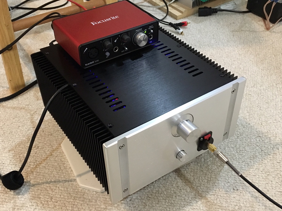
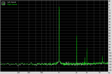
I connected Silicon Harmony to my Focsurite DAC (capable of 192kHz at 32bit), and played a high res 176k FLAC file of Spyro Gyra's Dreams of Toledo. Wow. The better the source, the better it sounds. Here is the FFT profile of this amp into 33ohms. Predominantly H2 distortion at -66dB and H3 at -90dB. Not much else. There is a bit of odd noise sneaking in from one of the DC step ups which may be going bad as I can hear a slight whining noise from it. Will change those out shortly for some new ones with a proper heatsink.

I love the dynamic range of this amp. From the blackest blackest blacks (no noise when no music playing even at full volume - cannot tell it is turned on), the how hard it hits you when the headphone frame recoils on a kick drum.
I love the dynamic range of this amp. From the blackest blackest blacks (no noise when no music playing even at full volume - cannot tell it is turned on), the how hard it hits you when the headphone frame recoils on a kick drum.
Attachments

Last edited:
I connected Silicon Harmony to my Focsurite DAC (capable of 192kHz at 32bit), and played a high res 176k FLAC file of Spyro Gyra's Dreams of Toledo. Wow. The better the source, the better it sounds. Here is the FFT profile of this amp into 33ohms. Predominantly H2 distortion at -66dB and H3 at -90dB. Not much else. There is a bit of odd noise sneaking in from one of the DC step ups which may be going bad as I can hear a slight whining noise from it. Will change those out shortly for some new ones with a proper heatsink.
I love the dynamic range of this amp. From the blackest blackest blacks (no noise when no music playing even at full volume - cannot tell it is turned on), the how hard it hits you when the headphone frame recoils on a kick drum.
Wow that's a sexy beast! May I know what would be its rated power at 50ohm?!
so I think in fiddling with capacitors I've killed something on my board.
on the "b" channel the mosfet reading and jfet readings are off. in this case would I be right in saying the jeft is stuffed which is causing the mosfet readings to be off, and try swapping the jfet first?
on the "b" channel the mosfet reading and jfet readings are off. in this case would I be right in saying the jeft is stuffed which is causing the mosfet readings to be off, and try swapping the jfet first?
I was wondering mate!, as to what happened to Silicon Harmony..
BTW nice case, and controls, yummy!
lots and lots of work!
Prasi, I'm so glad you've found a "change of heart" to XRK's AC-coupled designs and now realize they are "state-of-the-art designs and possibly yummy".😀
Yes mate, I was wondering myself just what happened to Silicon Harmony?😕
Keep up the good work Prasi!

can't edit my previous post - forgot to put in voltage readings, which are:
measurements:
On the B mosfet: 15V (battery voltage) on pin 1 & 2, 12V on pin 3.
B jfet: G & S 0V, D 15V
readings on A channel seem to more or less follow the values on the LTS sim posted on p67.
However ,
R3b is 0V, R7b is 12V - not sure what to make of this? resistance readings are as normal though.
Again channel A readings are normal
ideas?
All I did between it working and not working was replace the output caps...lol
Last edited:
Prasi, I'm so glad you've found a "change of heart" to XRK's AC-coupled designs and now realize they are "state-of-the-art designs and possibly yummy".😀
Yes mate, I was wondering myself just what happened to Silicon Harmony?😕
Keep up the good work Prasi!
I don't think Prasi ever said he did not think SE Class A wasn't state of the art. In fact, he is the layout artist on Silicon Harmony - so not sure what you are talking about.
can't edit my previous post - forgot to put in voltage readings, which are:
measurements:
On the B mosfet: 15V (battery voltage) on pin 1 & 2, 12V on pin 3.
B jfet: G & S 0V, D 15V
readings on A channel seem to more or less follow the values on the LTS sim posted on p67.
However ,
R3b is 0V, R7b is 12V - not sure what to make of this? resistance readings are as normal though.
Again channel A readings are normal
ideas?
All I did between it working and not working was replace the output caps...lol
I think I have seen this before on BabySupra's first build. Check for a cold solder joint or loose connection on the resistors below the JFET (R4, R5). If they are open (bad joint), it makes gate of mosfet same as rail. Use soldering iron to retouch the SMT joints and use DVM to confirm that there is voltage across R5 showing current is flowing. Should be same as current across R3.
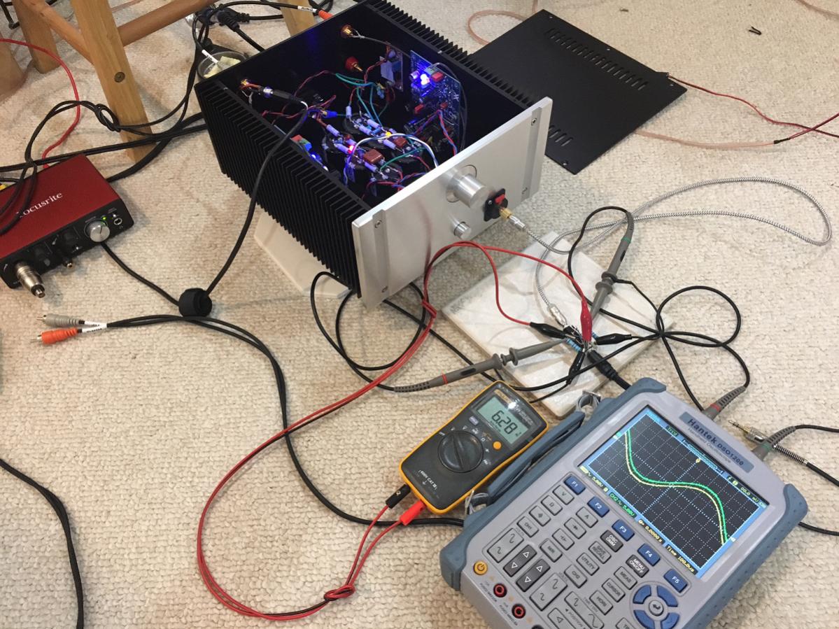
Wow that's a sexy beast! May I know what would be its rated power at 50ohm?!
I just ran a test with 51R power resistors and amp Vcc set at 29.0v. With the O-scope showing the trace as un-clipped, the Fluke showed 6.28vac. That's about 773mW (circa 800mW) into 51 ohms. Since the amp was designed for 8ohms, it should put out exactly 5w unlcipped into 8ohms. So you may say 800mW is wimpy compared to a Class AB opamp like an LME49600, but that's pure Class A operation - the only kind of operation possible with a single ended Class A amp. Heatsink temp is still a safe 55 deg C. We are dissipating 32w from each channel to get 800mW into 51ohms or 2.5% efficiency! 😀
Attachments

Last edited:
hey thanks. according to measurements it should be working now - will test it with headphones in a sec.
touched up solder joints - no dice. replaced jfet - same readings. then i found out i didn't solder one leg of the replacement jfet. silly me. too eager haha
touched up solder joints - no dice. replaced jfet - same readings. then i found out i didn't solder one leg of the replacement jfet. silly me. too eager haha
For the record, I never did say anything about SE Class A being not a state of the art.
Heck, Its designed by xrk in collaboration with AKSA! and I did the layout!.
Mods, such trolls doing such unprovoked and unnecessary personal jibes and attacks and that too repeatedly, should be banned from the forum permanently.
Heck, Its designed by xrk in collaboration with AKSA! and I did the layout!.
Mods, such trolls doing such unprovoked and unnecessary personal jibes and attacks and that too repeatedly, should be banned from the forum permanently.
My first all aluminum Class A case - a surprise is that the whole case acts like a heatsink since aluminum conducts so well. The top, bottom, front and back panels all feel warm and the solid aluminum volume knob too. Amazing how much heat the equivalent of a 75w lightbulb puts out.
quick tidbit
I fitted 2x 1000uF KZ , and they seem to be giving more substance and digging deeper in the bass as compared to the 2200uF KA.
however - the KZ amp does have 2700uF rail caps vs 2200uF on the KA amp, and KZ is the one that is running at higher bias.
I fitted 2x 1000uF KZ , and they seem to be giving more substance and digging deeper in the bass as compared to the 2200uF KA.
however - the KZ amp does have 2700uF rail caps vs 2200uF on the KA amp, and KZ is the one that is running at higher bias.
and KZ is the one that is running at higher bias.
I would like to believe that it is the higher bias, not the caps that makes the difference?
yeah potentially/probably. im not saying its the caps making all the difference lol, im still kinda skeptical, just trying diff caps to see what happens. KZ and KA are two different boards so can't be bothered matching biases, but will do further cap swapping on the KZ board.
yeah potentially/probably. im not saying its the caps making all the difference lol, im still kinda skeptical, just trying diff caps to see what happens. KZ and KA are two different boards so can't be bothered matching biases, but will do further cap swapping on the KZ board.
Keep on cap rolling - I am also interested in the results. Stellarelephant and X have uncovered some interesting findings - like bypassing with a 10uF Silmic rather than a film cap on the output.
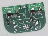
I am a little late to the party. I have had the board and parts for months, life just got in the way for a while. So, my first ever SMD soldering. Used the hotplate method, no frills just works great.
On to finishing the build.
Thanks to all that have gone before me.
On to finishing the build.
Thanks to all that have gone before me.
Attachments
Drpro,
Don't forget to put in a value for RL. At least 600R if you want to not have turn on pop if you turn on first then plug in phones. It helps ensure stability too.
Don't forget to put in a value for RL. At least 600R if you want to not have turn on pop if you turn on first then plug in phones. It helps ensure stability too.
- Home
- Group Buys
- xrk971 Pocket Class A Headamp GB