After 2 hours of listening on the new amp sans film bypass caps and Silmic II 100uF doing the bypass duties for the 470uF Nichicon AK - I can say that I really like the sound. I have not A/B'd it but, subjectively, the high hats and rim shots on jazz trios sound really natural. Very clear and without a bit of glare or harshness. The stand up bass strings sound great too. I can hear the sound the fingers make as they rub against the helical wire jacket on the large strings and it makes a soft scraping noise. I am listening to Esperanza Spalding playing the track "The Peacocks" and it sounds great. Perhaps the best that I have heard it. I got rid of the 47uF 25v SMT elco. Doesn't need it and probably detracts from Silmic. Also, very articulate and clear deep bass is produced without strain on my OB-1's (rated 55ohms but nominally 70ohms according to innerfidelity).
Since you did away with the small film bypass altogether, how would whacking in a Silmic of desired capacitance and calling it a day work? (i.e no bypass at all) Based on the logic that the silmic can handle mids and highs well, the large(r) capacitance should also allow it to handle lows fine?
My thoughts too. If space (in a tin) is not an issue, would a 470uF Silmic bypassed with another 47uF Silmic not be the ultimate? 🙂
hey the white altoids tin looks pretty cool, should hang onto this one 😉
Yep, don't sell this one. The retro look is cool. 🙂
Happy tweaking and listening!
My thoughts too. If space (in a tin) is not an issue, would a 470uF Silmic bypassed with another 47uF Silmic not be the ultimate? 🙂
Don't know if a Silmic needs to be bypassed by a Silmic. 🙂
If I had a 470uF Silmic, I would look for a polyethylene cap as bypass. Or maybe a 1000uF OSCON and 470uF Silmic would be the ultimate? Low ESR for deep bass and Silmic for mids and highs.
I bet that new amp does sound good, X! Love the looks, too.
I agree that it MIGHT be just as good or better to use a single larger value Silmic. Funch did it! Linking his pic from the Head-Fi thread:

It looks pretty awesome and probably sounds it. It maxes out the PCB space completely and will only fit a 16V rated Silmic for the 470uF. Maybe I am too hung up on sticking around 20-25% of cap rating...theoretically it's an advantage but a listening test between something like what X and I are running now and a setup Funch's would be the best way to decide. For you guys with high impedance cans, you could probably get the best of both worlds and use a smaller capacitance 25V 220uF Silmic or something.
Another potential drawback of these huge Silmics is that I think they might limit you to using 10mm diameter rail caps. I'm really wanting to try out these fat 12x20mm 1500uF Panasonic FR caps on my next build. Funch, do you think they'd fit alongside those big Silmics?
Last edited:
Finally, I happened to find in my fly fishing tackle bag (took my son fishing yesterday) an old Altoids tin that I used to keep flies in. It is painted white on the bottom half and says "Made in Britain". I guess Altoids used to be made in Britain?!
Yep, I have a stash of maybe 50 of the white-bottomed tins from around 20 years ago. According to Wikipedia, Altoids were originally manufactured in Bridgend, Wales but are now made in Chattanooga, TN. The new gold-bottomed tins simply say Altoids are distributed out of Chicago.
Last edited:
Yep, don't sell this one. The retro look is cool. 🙂
Happy tweaking and listening!
Agreed. It's a keeper, that's for sure. 🙂
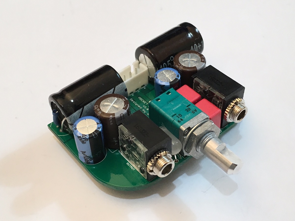
Both looks and sounds great.
Hi X,
I just finished my first board and powered it up.
LED is lit, but no sound is coming through.
where should I start troubleshooting?
I just finished my first board and powered it up.
LED is lit, but no sound is coming through.
where should I start troubleshooting?
Hi X,
I just finished my first board and powered it up.
LED is lit, but no sound is coming through.
where should I start troubleshooting?
What batteries are you using? If rechargeable 9v cells, is LED lit brightly? If not, try clicking power on/off 2-5 times. Sometimes battery protection circuit kicks in to shut down battery to protect it from what it thinks is a short caused by in rush to rail caps.
If lit, check with DVM voltage on pin 2 of mosfet to make sure it is getting juice. Should be circa 15-16v. Then check pin 3 to see what is output of mosfet should be circa 6-7v corresponding to 50mA to 60mA bias. Then check voltage across R3, the 1k resistor feeding JFET. Should be about 6-7mV corresponding to 6-7mA. If all these check out you should get sound.
If pin 2 of mosfet measures either 0v or 15v then mosfet was zapped by ESD. If R3 doesn't have voltage then JFET is dead.
My guess is your batteries shutdown or are DOA.
Big culprit is battery. Put in alkaline cells to be sure they don't auto shutdown on you.
Last edited:
What batteries are you using? If rechargeable 9v cells, is LED lit brightly? If not, try clicking power on/off 2-5 times. Sometimes battery protection circuit kicks in to shut down battery to protect it from what it thinks is a short caused by in rush to rail caps.
If lit, check with DVM voltage on pin 2 of mosfet to make sure it is getting juice. Should be circa 15-16v. Then check pin 3 to see what is output of mosfet should be circa 6-7v corresponding to 50mA to 60mA bias. Then check voltage across R3, the 1k resistor feeding JFET. Should be about 6-7mV corresponding to 6-7mA. If all these check out you should get sound.
If pin 2 of mosfet measures either 0v or 15v then mosfet was zapped by ESD. If R3 doesn't have voltage then JFET is dead.
My guess is your batteries shutdown or are DOA.
Big culprit is battery. Put in alkaline cells to be sure they don't auto shutdown on you.
Hi X,
thank you for the fast reply!
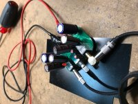
I've attached my board for reference.
I am using an open frame 18V 40W power supply, and I am clamping the wires to the outer battery pins (see pic), I ignored the two inner pins, is this correct?
I wore two anti-static bands, one is the cable-less with a cap, and the other is the old school wire attached to an exposed metal switch on my PC.
I had trouble soldering the mosfet and jfet, and I am worried they may be damaged by heat?
I will go measure and report back.
EDIT:
measured 2.95V and 3.11V across mosfet pin 3, and 0V and 0V across pin2
and measured 0V across R3
what are the odds that I damaged ALL of my FETs???
Attachments

Last edited:
Pin 2 of ZVN4306 should be same as PSU or 18v. Are you measuring relative to GNd (0v)?
So strange that you have 3v on pin 3 but 0v on pin 2. Is your PSU putting out 18v - that should show 18v at pin 2 (1 is pin left, pin 3 is same as 4 resistors next to mosfet). Pin 2 is same as big tab soldered to heatsink on PCB.
I would suggest you solder some wires to the battery input pins (on SMT side) and connect to PSU. The alligator clips may be giving a bad connection.
When you measure across R3, I literally mean across it: DVM probes on either side of R3, which, btw for the top of R3, is the same as big tab on mosfet pin 2.
Last edited:
Pin 2 of ZVN4306 should be same as PSU or 18v. Are you measuring relative to GNd (0v)?
So strange that you have 3v on pin 3 but 0v on pin 2. Is your PSU putting out 18v - that should show 18v at pin 2 (1 is pin left, pin 3 is same as 4 resistors next to mosfet). Pin 2 is same as big tab soldered to heatsink on PCB.
I would suggest you solder some wires to the battery input pins (on SMT side) and connect to PSU. The alligator clips may be giving a bad connection.
When you measure across R3, I literally mean across it: DVM probes on either side of R3, which, btw for the top of R3, is the same as big tab on mosfet pin 2.
both channels are silent.
I measured the following:
power = 18V
C1 = 18V (both caps)
C2 = 12V (both channels, both A and B caps)
C3 = 18V
C4 and C5 are all 18V
If C1 measures 18v that is not good. It should be about 1.5v - so it looks like your two JFETs are dead and conducting through the gate - but even so should be less than 18v as there should be a drop across R3. But given that it is 18v, that says pin 1 of mosfet is 18v? In which case mosfet is fried. That is mosfet gate is shorted to Drain (pin 2). Looks like static zap.
Did you repeat mosfet pin measurments because pin 2 should be 18v. ?
Sorry that it's not working but you have to be really careful with ESD protection. Maybe try solder paste and hot plate approach?
Please repeat measurement relative to GND: pins 1,2,3 of mosfet.
Thanks.
Did you repeat mosfet pin measurments because pin 2 should be 18v. ?
Sorry that it's not working but you have to be really careful with ESD protection. Maybe try solder paste and hot plate approach?
Please repeat measurement relative to GND: pins 1,2,3 of mosfet.
Thanks.
Last edited:
If C1 measures 18v that is not good. It should be about 1.5v - so it looks like your two JFETs are dead and conducting through the gate - but even so should be less than 18v as there should be a drop across R3. But given that it is 18v, that says pin 1 of mosfet is 18v? In which case mosfet is fried. That is mosfet gate is shorted to Drain (pin 2). Looks like static zap.
Did you repeat mosfet pin measurments because pin 2 should be 18v. ?
Sorry that it's not working but you have to be really careful with ESD protection. Maybe try solder paste and hot plate approach?
Please repeat measurement relative to GND: pins 1,2,3 of mosfet.
Thanks.
my bad, I measured the FETs wrong!!!
for both MOSFETs, now relative to GND:
S = 12V
D = 18V
G = 18V
for right JFET, now relative to GND:
all 3 pins = 18V
for left JFET, now relative to GND:
S and G = 2V
D = 0V
cap measurements are across the caps:
power = 18V
C1 = 18V (both caps)
C2 = 12V (both channels, both A and B caps)
C3 = 18V
C4 and C5 are all 18V
I think your MOSFETs are bad. Your JFETs may be ok. Try changing out the MOSFETs first and see what you get. When you measure caps measure relative to ground and not across pins. Positive pins of C2 should be same as Source on MOSFET. Positive on C1 (facing JFET) should be about 1.5v if it's working right.
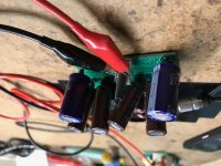
Are the MOSFET heat dissipation areas electrically connected to anything? It looks to me like babysupra may have a solder bridge between one MOSFET drain and the cooling pad. This might explain why one channel misbehaves, but not the other.
Can you post close-up pictures of both sides of the board?
Can you post close-up pictures of both sides of the board?
Correction to my post #636:
The beefy wire leads of the Nichicon Muse KZ actually DO FIT through the holes in this PCB. I discovered that I had a teeny tiny bit of solder left in one of the holes, which my desoldering braid had not quite picked up first pass. Anyway, after removing the solder speck, I got them in. Now to listen some more...
BTW Babysupra I wish you luck with your troubleshooting.
+1 good luck on debugging Babysupra.
Let me know if you need another PCB to retry it. I can send you a replacement for cost of shipping as I do want you to come out of this successfully. You might consider a board with all SMTs installed and tested and you just install through hole parts.
Let me know if you need another PCB to retry it. I can send you a replacement for cost of shipping as I do want you to come out of this successfully. You might consider a board with all SMTs installed and tested and you just install through hole parts.
- Home
- Group Buys
- xrk971 Pocket Class A Headamp GB