I ordered these heatsinks from mouser: EV-T220-38E Ohmite | Mouser Ireland
the order should be here in the next couple days to check but im pretty sure they'll be ok
the order should be here in the next couple days to check but im pretty sure they'll be ok
This works too:
Heat Sink To-220/202 3 Holes Black Anodized 2.50" X1.38" X.50 10 pcs | eBay
These are smaller but convenient as holes are threaded so no nuts required, also solid area for better conduction, but smaller size.
5PCS 30*34*12MM Triode IC heat sink For TO-220 Aluminum | eBay
Heat Sink To-220/202 3 Holes Black Anodized 2.50" X1.38" X.50 10 pcs | eBay
These are smaller but convenient as holes are threaded so no nuts required, also solid area for better conduction, but smaller size.
5PCS 30*34*12MM Triode IC heat sink For TO-220 Aluminum | eBay
Last edited:
No ebay! 😱 I'm hoping to get ONE shopping cart.. And for all parts to arrive at once. These customs people are atrocious..
Will select FEDEX or DHL or something.. That part looks nice Laserscape 😀 show pictures of the build once done.
Will select FEDEX or DHL or something.. That part looks nice Laserscape 😀 show pictures of the build once done.
Super long time lurker but I've been talking to you on the Etsy side for the last couple of weeks (JasonA).. and I'd also been interested in the full parts kit as well! 😉
Thanks!
Jason
Thanks!
Jason
Thanks for the input Jason. I will see what I can do about a kit. They take time to put together, just so busy with so many projects.
Well the last bits of hardware including the 5525 DC jacks arrived today, if I have time hope to have it up and running this weekend!
I have tons of those 5.5mm barrel jack connectors - must have been one of those Aliexpress bag of 50 for $3 orders. I would have thrown one in for you if I knew.
I am surprised no one is finishing their builds yet. This amp is a quick and easy build. Pretty much guaranteed to work the first time.
Well the last bits of hardware including the 5525 DC jacks arrived today, if I have time hope to have it up and running this weekend!
How is the build going?
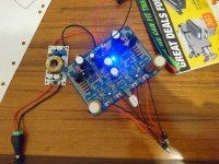
Had to call it a night, almost done, just the FETs to go.
Was thinking of having it "open" & screwed onto an acrylic sheet. Anyone have any ideas on how/where to mount the jacks if I do this?
Thought I could secure the switchraft jacks onto the PCB but my idea wasn't secure enough.
Acrylic sheet: 2 5mm Plastic Transparent Board Perspex Panel thickness 1pcs Clear Acrylic Perspex Sheet Cut-in Window-Dressing Hardware from Home Improvement on Aliexpress.com | Alibaba Group
Alum angle stock makes very handy “panels” for mounting jacks, pots, bananas, RCA’s etc. they are especially suite for open gram “amps on a plank” constructions. The plexiglas is a great idea and looks better than wood. Give it a try. I have so many amps that if I were to case each one in an aluminum enclosure it would be prohibitively expensive and more than that - time consuming. So far I have only two real cases for my amps and the big 4U Dissipante is made to be easily serviceable and amps switched in and out.
For headphone amps, cases with pre-cut RCA, headphone out, volume pot and AC mains input are great options. You still have to drill holes for the PCB standoff’s, PSU, etc. and amp heatsinking if outputs. It becomes a full day project to just to put an amp in a case.
For headphone amps, cases with pre-cut RCA, headphone out, volume pot and AC mains input are great options. You still have to drill holes for the PCB standoff’s, PSU, etc. and amp heatsinking if outputs. It becomes a full day project to just to put an amp in a case.
I think I have an idea of what you mean - are they on aliexpress/ebay or the local hardware store
found this as well - undecided if I should give this a shot 😛 : Right Angle Bending Machine Easy Operation Acrylic Hot Bending Machine 3D Luminous Sign Arc Shape Bender Angle Shaping Device-in Bending Machinery from Tools on Aliexpress.com | Alibaba Group
found this as well - undecided if I should give this a shot 😛 : Right Angle Bending Machine Easy Operation Acrylic Hot Bending Machine 3D Luminous Sign Arc Shape Bender Angle Shaping Device-in Bending Machinery from Tools on Aliexpress.com | Alibaba Group
Last edited:
I got it singing! 10.1 &10.28v (20.22v Vcc after the multiplier and filter) across each resistor bank with the stock values!
Is it worth balancing out?
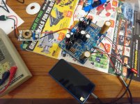
Haven't worked out how to attach pictures from my phone yet so that'll have to wait
Maybe because of the capacity for the board to absorb heat, it's very difficult to remove components/solder from clogged holes , the solder never quite gets hot enough. (iron at 400C)
Was thinking of swapping caps (and resistors) but I don't think it'll be possible...
Is it worth balancing out?
Haven't worked out how to attach pictures from my phone yet so that'll have to wait
Maybe because of the capacity for the board to absorb heat, it's very difficult to remove components/solder from clogged holes , the solder never quite gets hot enough. (iron at 400C)
Was thinking of swapping caps (and resistors) but I don't think it'll be possible...
Last edited:
Congrats! That’s pretty well balanced and perfect DC setpoints - don’t worry. Use a fat chisel tip to apply more heat for desolder.

Go to “advanced” reply, upload photos. Resize to smaller than 1200 pix wide to allow easier viewing.
Go to “advanced” reply, upload photos. Resize to smaller than 1200 pix wide to allow easier viewing.
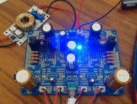
Nice work! Congrats on being the very first besides me to build the DCA. It was easy wasn’t it? You deserve a pat on the back for perfect DC bias with DC midpoint after MOSFET source at 1/2Vcc. Doesn’t get better than that so you will have the best possible clip performance. Meaning 500+mW into 50ohm cans! Not bad for pure SE Class A headphone amp with 2 actives and no choke loading. (For comparison, the PCA with 65mA bias only managed 50mW).

One thing to double check is the polarity on your audio input and outputs. The board exhibts mirror symmetry at the midpoint (left-to-right). So 4 jacks left to right are
+ve -ve / -ve +ve / +ve -ve / -ve +ve
Why? Because JPS64 designs for symmetry for best noise performance and for ground loops to be minimized. It makes for custom wired connectors though. So I think you need to flip polarity of left input and right output. Then your phase will be correct and soundstage will be much better.
Use a small sharp tip of an Xacto or needle to push the barb of the crimped JST connector down to pull it out. Lift barb back up a little and reinstall in correct order.
Last edited:
Thanks! The polarity looks wrong because I ordered the pre-crimped leads off ebay since I don't have the crimping tool. Not sure if the picture is clear enough to see, but there's one red and one black wire going to the ground lug 😉
Also if you look closer, the 68R resistor is actually 680 - I misread the BOM! Theres a small 1/8W 75R underneath to bring it back to 68R
Also if you look closer, the 68R resistor is actually 680 - I misread the BOM! Theres a small 1/8W 75R underneath to bring it back to 68R

Thanks! The polarity looks wrong because I ordered the pre-crimped leads off ebay since I don't have the crimping tool. Not sure if the picture is clear enough to see, but there's one red and one black wire going to the ground lug 😉
Also if you look closer, the 68R resistor is actually 680 - I misread the BOM! Theres a small 1/8W 75R underneath to bring it back to 68R
Ok, I see that now. You caught that. Better to pull them out and resolved in correct color. But if it doesn’t bother you that’s cool.
- Home
- Group Buys
- xrk971 Desktop Class A (DCA) Headphone Amp