Hi. Can i use MPF102 or 2sk30? Can you help with the resistor adjustment for MPF102 or 2sk30?Over in the Yarra thread we discuss the new setpoints for PCA/DCA daughterboard (same as DCA in principle) either the 2SK209GR or 2SK170BL(available from GB’s) or LSK170BL. Those 2SK209GR’s are Toshiba JFETs and still available.
The YARRA Preamplifier/HPA for Melbourne DB Group Buy
Use IRF610 or Fairchild FQP4N20 work very well too.
You will wait a long time since I have a lot of the original boards left. 🙂
Thank you so much
I don’t have models for those actives. You could search for the models yourself and put it into the LTSpice model. If you send me the schematic .ASC file with the models I can help you adjust it and optimize it. But I don’t have time to go find models and get it all to work for you. That’s your DIY part. Or you can use the parts I specified and no tweaking or adjustments necessary.
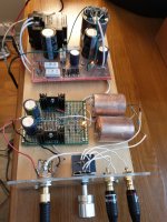
I built this up on veroboard with 2sk209gr as in the above schematic with a linear power supply. Sounds fantastic on my Grados! Very smooth and natural. Not quite as musical and nuanced as my much more expensive and complex 4p1l tube amp, but very good indeed. Thanks for sharing the design. Notice the gigantic 4.7uF Obbligato Copper input caps left over from a tube amp build.
Attachments
Rman,
Fantastic plank amp! That’s how most of my amps look. 😛
Glad that is sounds great. It works superbly as a preamp as well. Those caps are superb looking. Probably cost as much as BOM of one of these amps to build.
Cheers,
X
Fantastic plank amp! That’s how most of my amps look. 😛
Glad that is sounds great. It works superbly as a preamp as well. Those caps are superb looking. Probably cost as much as BOM of one of these amps to build.
Cheers,
X
Hi X. Thank you for the reply.
I want to build this amp as a standalone device. I decided to use 2sk170, based on this schematic and using resistor setting from this post
https://www.diyaudio.com/community/...or-melbourne-db-group-buy.334457/post-5898779
The question is:
1. Is the value correct for 32 ohm headphones?
2. What is the output impedance for this particular setup?
3. On the description it says that R102+R104 = 2K. That means 1K each, right?
BTW, am using cap multiplier on this thread.
Thank you
Attachments
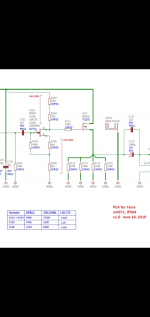
The schematics says R103+R104=930ohms for 2SK170BL. That means the sim equals 930ohms not each. So 900ohms plus 30ohms, etc… in series.Hi X. Thank you for the reply.
I want to build this amp as a standalone device. I decided to use 2sk170, based on this schematic and using resistor setting from this post
https://www.diyaudio.com/community/...or-melbourne-db-group-buy.334457/post-5898779
The question is:
1. Is the value correct for 32 ohm headphones?
2. What is the output impedance for this particular setup?
3. On the description it says that R102+R104 = 2K. That means 1K each, right?
BTW, am using cap multiplier on this thread.
Thank you
It will work for 32ohm headphones but that is the limit for 125mA bias current. Change output cap to 2200uF for 32ohm load.
Output impedance requires a simulation but from memory I seem to recall it’s in the 3-5 ohms range.
Can i increase the bias to 150mA to lower the output impedance?The schematics says R103+R104=930ohms for 2SK170BL. That means the sim equals 930ohms not each. So 900ohms plus 30ohms, etc… in series.
It will work for 32ohm headphones but that is the limit for 125mA bias current. Change output cap to 2200uF for 32ohm load.
Output impedance requires a simulation but from memory I seem to recall it’s in the 3-5 ohms range.
What is the effect 150mA bias to the harmonic distortion?
Am planning to use 2 transistor CCS, is that change the harmonic distortion?
Thank you
The increase bias current will decrease harmonic distortion of driving lower impedance loads. Adding a CCS will significantly reduce distortion.
Yes, input cap is as big as you want. But 2.2uF film cap is about perfect. I sometimes use 10uF Silmic II but that’s just convenience and they are tiny. Output should be at least 2200uF electrolytic and bypass with a 2.2uF film cap.
Hi, pocket version have better gain than desktop version ? I compare two of them, the pocket version only need volume 2-3, than the desktop version need volume 7-8.Yes, input cap is as big as you want. But 2.2uF film cap is about perfect. I sometimes use 10uF Silmic II but that’s just convenience and they are tiny. Output should be at least 2200uF electrolytic and bypass with a 2.2uF film cap.
If you have the same resistor network the gain should be the same. Gain is (R103+R104)/(R105+R106). The JFETs may have different Idss and that may affect the relative volume between the two amps. But if you match Idss between both amps. They should have same gain.
Pink,A few more questions...
1) It looks like BF862 is an obsolete part. Is there a good replacement, and if so, what is it and does it require and resistor values to be changed from what's on the BOM?
2) for V111 and V112, the BOM shows IRF610 in Column 2 and IRF512 in Column 3. Does that mean either will work, with the resistor values on the BOM? It looks like IRF610 is currently available, while IRF512 is obsolete.
3) Also, I saw you mention that the next run of DCA boards might have solder mask over all the vias. If I wanted to wait for that next version of the board with the "tented vias", how long might I be waiting?
Did you ever build the DCA? I'm considering it and have been stumped by the BOM . . . if you have a more or less complete/up to date BOM, send along.
Thanks!
Tell me what has you stumped in the BOM? A lot of the parts can be substituted. Just make sure capacitor voltages are observed. Use metal thin film resistors in audio signal path. Carbon film resistors can also work well. Its not a finicky circuit so there is wiggle room.
Here is a more detailed BOM for the DCA with capacitor dimensions etc so you can make informed choices for substitutions. Feel free to substitute the boutique Mundorf caps with something else. Many different lead spacings work as it is axial and you can bend the wires to fit. Use metal thin film resistors if possible, especially for parts in the audio signal path.
| Part | Value | Device | Package | Description | |
| C101 | 10 µ0 | CPOL-EUE3.5-8 | E3,5-8 | POLARIZED | Electrolytic 3.5mm pitch x 8mm dia |
| C101A | C22/10 | C22.5B10 | CAPACITOR | Film 22.5mm pitch x 10mm width | |
| C101B | C27/17 | C27.5B17 | CAPACITOR | Film 27.5mm pitch x 17mm wide | |
| C101C | 0 µ1 | MKC1860-0U1 | MKC1860-0U1 | Wima part number | |
| C101D | 10 µ0 | MCAP250V10U | MCAP250V10U | Fidelity | Mundorf Mcap part number |
| C102 | 10 µ0 | CPOL-EUE3.5-8 | E3,5-8 | POLARIZED | Electrolytic 3.5mm pitch x 8mm dia |
| C102A | C22/10 | C22.5B10 | CAPACITOR | Film 22.5mm pitch x 10mm wide | |
| C102B | C27/17 | C27.5B17 | CAPACITOR | Film 27.5mm pitch x 17mm wide | |
| C102C | 0 µ1 | MKC1860-0U1 | MKC1860-0U1 | Wima part number | |
| C102D | 10 µ0 | MCAP250V10U | MCAP250V10U | Fidelity | Mundorf Mcap part number |
| C111 | 1 µ0 | C5/5 | C5B5 | CAPACITOR | Film 5mm pitch x 5mm wide |
| C111A | C10/6 | C10B6 | CAPACITOR | Film 10mm pitch x 6mm wide | |
| C111B | C15/8 | C15B8 | CAPACITOR | Film 15mm pitch x 8mm wide | |
| C112 | 1 µ0 | C5/5 | C5B5 | CAPACITOR | Film 5mm pitch x 5mm wide |
| C112A | C10/6 | C10B6 | CAPACITOR | Film 10mm pitch x 6mm wide | |
| C112B | C15/8 | C15B8 | CAPACITOR | Film 15mm pitch x 8mm wide | |
| C113 | 2200uF | CPOL-EUE7.5-18 | E7,5-18 | POLARIZED | Electrolytic 7.5mm pitch x 18mm dia |
| C113A | CPOL-EUE5-10.5 | E5-10,5 | POLARIZED | CAPACITOR, | Electrolytic 5mm pitch up to 18mm dia |
| C114 | 2200uF | CPOL-EUE7.5-18 | E7,5-18 | POLARIZED | Electrolytic 7.5mm pitch x 18mm dia |
| C114A | CPOL-EUE5-10.5 | E5-10,5 | POLARIZED | CAPACITOR, | Electrolytic 5mm pitch up to 18mm dia |
| C131 | 220 µ | CPOL-EUE5-13 | E5-13 | POLARIZED | Electrolytic 5mm pitch up to 13mm dia |
| C133 | 1 µ0 | C5/5 | C5B5 | CAPACITOR | Fil 5mm pitch x 5mm width |
| C134 | 2200 µ | CPOL-EUE5-13 | E5-13 | POLARIZED | Electrolytic 5mm pitch up to 13mm dia |
| C135 | 2200 µ | CPOL-EUE5-13 | E5-13 | POLARIZED | Electrolytic 5mm pitch up to 13mm dia |
| C141 | 2200 µ | CPOL-EUE5-13 | E5-13 | POLARIZED | Electrolytic 5mm pitch up to 13mm dia |
| C142 | 2200 µ | CPOL-EUE5-13 | E5-13 | POLARIZED | Electrolytic 5mm pitch up to 13mm dia |
| C143 | 1 µ0 | C5/5 | C5B5 | CAPACITOR | Film 5mm pitch x 5mm wide |
| C144 | 1 µ0 | C5/5 | C5B5 | CAPACITOR | Film 5mm pitch x 5mm wide |
| R101 | RK09L12B | RK09L12B | |||
| R102 | 100k | CMF-55 | CMF-55 | Dale 1/2W metal thin film 1% | |
| R103 | 100k | CMF-55 | CMF-55 | Dale 1/2W metal thin film 1% | |
| R104 | 22k0 | CMF-55 | CMF-55 | Dale 1/2W metal thin film 1% | |
| R105 | 22k0 | CMF-55 | CMF-55 | Dale 1/2W metal thin film 1% | |
| R106 | 1k1 | CMF-55 | CMF-55 | Dale 1/2W metal thin film 1% | |
| R107 | 68R0 | CMF-55 | CMF-55 | Dale 1/2W metal thin film 1% | |
| R108 | 250R | CMF-55 | CMF-55 | Dale 1/2W metal thin film 1% | |
| R109 | 1k1 | CMF-55 | CMF-55 | Dale 1/2W metal thin film 1% | |
| R111 | 68R0 | CMF-55 | CMF-55 | Dale 1/2W metal thin film 1% | |
| R112 | 250R | CMF-55 | CMF-55 | Dale 1/2W metal thin film 1% | |
| R113 | 47R0 | CMF-55 | CMF-55 | Dale 1/2W metal thin film 1% | |
| R114 | 47R0 | CMF-55 | CMF-55 | Dale 1/2W metal thin film 1% | |
| R115 | 270R | CMF60 | CMF60 | Dale 1W metal thin film 1% | |
| R116 | 270R | CMF60 | CMF60 | Dale 1W metal thin film 1% | |
| R117 | 270R | CMF60 | CMF60 | Dale 1W metal thin film 1% | |
| R118 | 270R | CMF60 | CMF60 | Dale 1W metal thin film 1% | |
| R119 | 270R | CMF60 | CMF60 | Dale 1W metal thin film 1% | |
| R121 | 270R | CMF60 | CMF60 | Dale 1W metal thin film 1% | |
| R122 | 270R | CMF60 | CMF60 | Dale 1W metal thin film 1% | |
| R123 | 270R | CMF60 | CMF60 | Dale 1W metal thin film 1% | |
| R124 | 270R | CMF-55 | CMF-55 | Dale 1/2W metal thin film 1% | |
| R125 | 270R | CMF-55 | CMF-55 | Dale 1/2W metal thin film 1% | |
| R131 | 10k0 | R-EU_0207/10 | 0207/10 | RESISTOR, | 2mm dia x 7mm long body, 10mm pitch axial |
| R132 | 220R | R-EU_0207/10 | 0207/10 | RESISTOR, | 2mm dia x 7mm long body, 10mm pitch axial |
| R133 | 1R5 | R-EU_0207/10 | 0207/10 | RESISTOR, | 2mm dia x 7mm long body, 10mm pitch axial |
| R134 | 0R47 | R-EU_0309/12 | 0309/12 | RESISTOR, | 3mm dia x 9mm long body, 12mm pitch axial |
| R135 | 0R47 | R-EU_0309/12 | 0309/12 | RESISTOR, | 3mm dia x 9mm long body, 12mm pitch axial |
| V101 | BF862 | SST201 | SOT23 | TEMIC | SOT23 SMT package |
| V102 | BF862 | SST201 | SOT23 | TEMIC | SOT23 SMT package |
| V103 | JFET | 2SK170 | TO92-DGS | Field | TO92 package |
| V104 | JFET | 2SK170 | TO92-DGS | Field | TO92 package |
| V111 | IRF610 | IRF512 | TO220BV | N-CHANNEL | TO220 package |
| V112 | IRF610 | IRF512 | TO220BV | N-CHANNEL | TO220 package |
| V131 | 1N4004 | 1N4004 | DO41-10 | DIODE | DO41 package axial 1A diode |
| V132 | IRF610 | IRF512 | TO220BV | N-CHANNEL | TO220 package |
| X101 | 22-27-2021-02 | 22-27-2021-02 | 6410-02 | CONNECTOR | Molex KK 2-pin 2.5mm pitch connector |
| X102 | 22-27-2021-02 | 22-27-2021-02 | 6410-02 | CONNECTOR | Molex KK 2-pin 2.5mm pitch connector |
| X111 | 22-27-2021-02 | 22-27-2021-02 | 6410-02 | CONNECTOR | Molex KK 2-pin 2.5mm pitch connector |
| X112 | 22-27-2021-02 | 22-27-2021-02 | 6410-02 | CONNECTOR | Molex KK 2-pin 2.5mm pitch connector |
| X131 | 22-27-2021-02 | 22-27-2021-02 | 6410-02 | CONNECTOR | Molex KK 2-pin 2.5mm pitch connector |
| X132 | AK500/2 | AK500/2 | CONNECTOR | unknown | 2-pin 10mm pitch screw terminal |
| X1011 | SK104 | SK104 | SK104 | HEATSINK | Fischer Heatsink SK104 |
| X1012 | SK104 | SK104 | SK104 | HEATSINK | Fischer Heatsink SK104 |
| X1031 | SK104 | SK104 | SK104 | HEATSINK | Fischer Heatsink SK104 |
I did not, sorry. Hopefully xrk can clear up any other questions you have. As you may have seen I too was confused by some of the nomenclature in the BOM, but I believe xrk answered those questions here in the thread.Pink,
Did you ever build the DCA? I'm considering it and have been stumped by the BOM . . . if you have a more or less complete/up to date BOM, send along.
Thanks!
- Home
- Group Buys
- xrk971 Desktop Class A (DCA) Headphone Amp