Sure, but some information will take even more work first. What parameters are you trying to find out?
True for best results. But knowing the values and schematic of the crossover will at least show you something close to the filter factor the designer was attempting to achieve.
Maybe just tracing the tweeter half would be enough to get close to the crossover frequency and attenuation.
Let's get serous here. Since you can plainly see the crossover, you can plainly see it has problematic parts like electrolytic capacitors and iron core inductors.
Even if you wanted to use such parts, even if you were OK with the complexity of the XO, and even if you can read their values off the labels, are you able to determine if the replacement parts you buy are close to their values and match L and R?
Clearly there's some low freq crossing over here. Today, many of us would handle a woofer or sub by bi-amping.
B.
Let's get serous here. Since you can plainly see the crossover, you can plainly see it has problematic parts like electrolytic capacitors and iron core inductors.
Nothing wrong with those parts if they are used in the right way.
Nothing wrong with those parts (iron core inductors and non-polarized electrolytics) if they are used in the right way.
What does that mean exactly?
And does everybody (or anybody) who builds with electrolytics and inductors have the means (and knowledge of calculus) to measure them to see if they are anywhere near their spec and to choose matching pairs L and R? And is the chemistry of your electrolytics "charged" to their rated capacitance at the minuscule varying voltages in a crossover?
B.
Last edited:
What does that mean exactly?
For example:
Electrolytic capacitors have higher ESR than a poly cap, so this needs to consider for best results. ESR is little tricky because the value is usually frequency dependent.
Iron cored inductors may saturate and distort at high loading situation and cannot reach their rated inductance at low loading situation (mainly the bulky ones, although not a big problem).
You need to be careful where and how to use and these passive parts works fine.
Last edited:
What does that mean exactly?
It means that if the designer knew what he was doing, electrolytics and iron core inductors may well be the right (if not the best) choice of capacitor or inductor types. It's just a question of what needs to be achieved.
And does everybody (or anybody) who builds with electrolytics and inductors have the means (and knowledge of calculus) to measure them to see if they are anywhere near their spec...
I don't see the logic here. How does the type of a capacitor or an inductor relate to the equipment and knowledge available in a workshop?
...and to choose matching pairs L and R? And is the chemistry of your electrolytics "charged" to their rated capacitance at the minuscule varying voltages in a crossover?
What does that mean exactly?
As YSDR cogently explained, electrolytic capacitors and iron core inductors are swell little elements but not for crossovers.
Electrolytics have giant tolerance and can be off by 50% and then need to be formed when electric currents start flowing through them. Other capacitors are stable and they can come with 10% tolerance.
Now, with all the obsessive attention to careful design and issues like phase and time alignment that goes on in this forum, you just can't install a part that could be 50% wrong. You need to measure your components and match L and R.
electrolytic capacitors and iron core inductors are swell little elements but not for crossovers.
No.
Electrolytics have giant tolerance and can be off by 50%...
There may be some electrolytics out there that come with large tolerance. But not all electrolytics are equal. Just look for parts with a 5% tolerance or so. Electrolytics are not inherently cheap junk that must be avoided at all costs.
For example, you might look at the xovers of the OSMC. The woofer filter uses a 6.8 mH / 0.2 Ohm inductor, a 120 uF capacitor, and some other parts. A typical 6.8 mH "air-core" inductor will have a DC resistance of more than 1 Ohm, which would result in a loss of efficiency and poor damping, affecting the bass tuning of the woofer / box. Only a very large and super expensive "air-core" inductor may get you well below 1 Ohm, but likely still higher than the 0.2 Ohm required for the OSMC. In contrast, an iron-core inductor will have low-enough DC resistance, allowing a better result. Except for loudspeakers that are designed for very high power levels (not the typical stuff we use at home), even a relatively small iron core will not saturate in normal use. Also, a 120 uF film cap will be unnecessarily expensive, where a suitable electrolytic will get you the same result at a fraction of the cost.
Would you really want to suggest "air core" inductors and film caps must be used for that?
Ok, time to get back on topic of the OP.
Last edited:
Ben. Do not drag this thread off topic as you have so often done elsewhere.
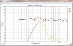
Gentlemen, let's stick to the topic at hand - which is the filter function of the crossover in question.

Gentlemen, let's stick to the topic at hand - which is the filter function of the crossover in question.
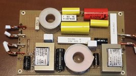
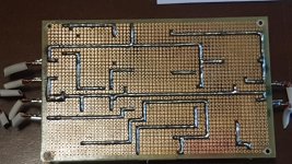
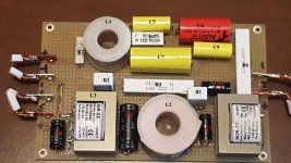
Hi is it possible to know electrical parameters of xover starting from pictures?
Yes... 🙂 I used Xsim and the zip file for V1 is attached.
There seems to be a lot of driver specific tuning. I used a DC28 tweeter and DC315 woofer as driver place holders. Do you know what the original drivers were?
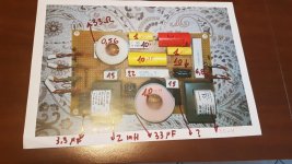
If you fill in the component values, using the reference designators, it would help understand the tuning.
If you have a multimeter (ohmeter) you can confirm the schematic connections. I flipped the bottom view so it matches the component view.
Attachments
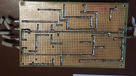
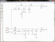
Many thanks DonVK! This is a great begin and help. Original drivers are Monacor SP6/108PRO and Monacor AIRMT-85 mounted on a tower cabinet with double bass reflex. Hoping this can help to clarify the problem.
No problem @ziocalepino, is there a problem you are trying to fix in the crossover?
Are you able to check the component values? Many of the value markings are hidden in the photos so I had to guess for some of them.
Are you able to check the component values? Many of the value markings are hidden in the photos so I had to guess for some of them.

- Status
- Not open for further replies.
- Home
- Loudspeakers
- Multi-Way
- Xover reverse engineering