That's perfect for component values.
Do you have an Ohmmeter to check the connections to see if the schematic is correct?
Do you have an Ohmmeter to check the connections to see if the schematic is correct?
Yes. I'll try tomorrow. I've downloaded Xsim so now I can try even if I've to undertand how to use it, expecially how input drivers parameters.
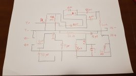
That schematic does not look right. I'll have another look later tonight with a few connections for you to check with your Ohmmeter.
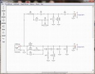
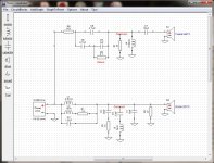
I had another look, and updated the component values. I made a few changes to the schematic to make it more readable.
Can you use your ohmmeter to measure R1, R2 I think the 15R is too high and should be 1.5R
What are you intending to do ? Change drivers ? Improve the Xover? I still don't know what the purpose is.
Can you use your ohmmeter to measure R1, R2 I think the 15R is too high and should be 1.5R
What are you intending to do ? Change drivers ? Improve the Xover? I still don't know what the purpose is.
Attachments
Last edited:
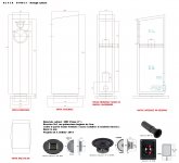
In short time I verify with multimeter R1 and R2 values. You made a great job, many thanks! Reasons for me to know everything possible about this xover are at least two. The first is practical, I used it on a double bass reflex tower enclosure with Monacor drivers (SP6-108PRO and AIRMT-85) without satisfaction. So I would like to try other configurations, for example Troels Gravesen 2-way cabinets, and I have to know xover values. The second is less "noble". The guy who has designed, built and sold me xover refuses to share tech infos about. He is a very strange man and there are no logical reasons for his attitude. It is a challenge for me at this point! Last question, could you please share XSim file of your last effort? Thanks!
OK now I understand, thanks.
The speaker needs to be designed as a system, so the cabinet, the drivers and XO all work together. If you mix and match you may not get very good results.
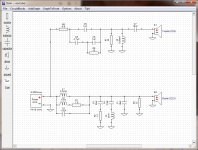
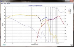
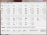
I have updated the schematic (V3) to include drivers that are now "closer" to what you have. Monacor does not publish full data (FRD, ZMA) files. Although you can create the files from graphs or measurements. You can see the FR mismatch which can be easily fixed in the XO. It still does not have the cabinet effects (tuning, baffle loss).
Your double bass reflex cabinet is tuned and is sensitive to the woofer parameters. If you can measure the cabinet and port dimensions we can check the tuning with HornResp. Then we can add the effects of the cabinet to the Xsim simulation and finally adjust the XO to get good performance.
The speaker needs to be designed as a system, so the cabinet, the drivers and XO all work together. If you mix and match you may not get very good results.
I have updated the schematic (V3) to include drivers that are now "closer" to what you have. Monacor does not publish full data (FRD, ZMA) files. Although you can create the files from graphs or measurements. You can see the FR mismatch which can be easily fixed in the XO. It still does not have the cabinet effects (tuning, baffle loss).
Your double bass reflex cabinet is tuned and is sensitive to the woofer parameters. If you can measure the cabinet and port dimensions we can check the tuning with HornResp. Then we can add the effects of the cabinet to the Xsim simulation and finally adjust the XO to get good performance.
Attachments
..Reasons for me to know everything possible about this xover are at least two. The first is practical, I used it on a double bass reflex tower enclosure with Monacor drivers (SP6-108PRO and AIRMT-85) without satisfaction. So I would like to try other configurations, for example Troels Gravesen 2-way cabinets, and I have to know xover values. The second is less "noble". The guy who has designed, built and sold me xover refuses to share tech infos about. He is a very strange man and there are no logical reasons for his attitude.
So we are clueless about about how we got here and where we are going and how many units you own or anything, despite the excellent efforts of DonVK.
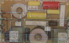
One thing that is obvious from the schematic is that you have (own, borrowed, rented??) a crossover made for some specific pair of drivers in specific cabinets (and possibly to compensate for those electrolytic and iron-core inductances). The circuit is full of little tricks to boost or cut at specific points, EQ, shelve, and trend the sound. It is the sort of crossover skilled manufacturers carefully cobble together based on listening and measurement tests before shipping to stores.
As DonVK is trying to tell you, you can plug in any drivers you want but the odds are just as good the specific boosts will make the sound worse as make it better. You would be better to rip out the tricks and install what's left as a plain-vanilla crossover.
B.
Last edited:
Attachments
Take a good look at Troels website and you'll understand that you cannot just use some random x-over with some other random loudspeaker. Troels knows what he's doing, so I'd suggest you just use the x-over designs he does for his speakers.
...As DonVK is trying to tell you, you can plug in any drivers you want but the odds are just as good the specific boosts will make the sound worse as make it better. You would be better to rip out the tricks and install what's left as a plain-vanilla crossover.
DonVK can explain how to convert to plain vanilla. Looks to me like all you need is two alligator clip leads to get almost all the way there. At least, that's a good place to start and then you can re-introduce the tricks one at a time and check the results*.
B.
* OK, prolly not worth bothering with
Here's the origina project and few examples of what I've in mind:
Let's check what you have now. You did not like the sound but maybe it can be fixed.
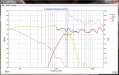
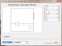
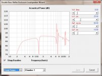
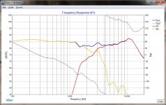
This is a HornResp model of the cabinet with the Monacor woofer. I also attached the HornResp record so you can import it and try it out HornResp Hornresp
Ignore the "spikes" they can be reduced with stuffing. The bass performance is poor because the cabinet and woofer were not tuned together. If we add in the baffle loss, the bass performance will look even worse. Is that one of the problems ?
Attachments
Last edited:
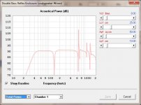
First of all, do not make any changes yet. This is just an "example" of the effect of just a few modifications. These may change as the simulation model gets more complete.
The cabinet's lower adjustable tuning port, was shortened to 100mm.
The XO has a few disconnected components based on drivers "like" yours.
The cabinet's lower adjustable tuning port, was shortened to 100mm.
The XO has a few disconnected components based on drivers "like" yours.
Attachments
How can I obtain FRD and ZMA data from graphs? I've seen tah in FRD there are frequency, dB and phase values, and in ZMA frequency, amplitide and phase. Generally SPL graph is available so frequency and dB are easy to obtain. What about others?
There are a few ways, assuming the manufacturer has decided to not publish basic data on their products.
If you already have the driver you can use REW, a soundcard and a simple resistor circuit to generate the ZMA file. You will also need a mic (calibrated is preferred) in order to generate the FRD files. It is difficult to check/adjust your designs without a mic so its a good idea to have one anyways.
If you want the data before deciding on which driver to buy there are a few routes. Sometimes you can find this data from sites like DIYaudio. Otherwise you need to "generate" it by foraging for graphs and extracting from similar items. The FRD format is [ Freq(Hz), SPL(dB), Phase (deg)] per line and the ZMA format is [ Freq(Hz), ImpMag (Ohms), Phase (deg)] per line. As you noticed, you can often you can find the graphs for Freq SPL and Impedance Magnitude but the phase is missing from both curves.
To "create" your own files. Extract the SPL and ImpMag data from published graphs using a program like Engauge Releases * markummitchell/engauge-digitizer * GitHub which allows you to curve trace and generate a space delimited text file. Then you need to add the acoustic and electrical phase information. Find a driver of similar size, resistance, inductance, sensitivity and you will notice the electrical phase varies from approx +60deg to -60deg centered about the resonance point. This phase curve can to be used as an approximation. The acoustic phase is less predictable but will follow a similar pattern up to where the cone breakup occurs. The curve trace can have as many sample points as you want and Xsim will linear interpolate between samples.
I've purchased FRD and ZMA data for my drivers. Is it better to start a new thread at this point, to have suggestions on cabinet project? Or go on here?
I've purchased FRD and ZMA data for my drivers.
You had to pay for this!? Wow...
- Status
- Not open for further replies.
- Home
- Loudspeakers
- Multi-Way
- Xover reverse engineering