@Lorien
After so many years of experience with this board 👏
How far do you conclude that regulators make a difference?
Is LP5907 really good for digital circuits(3v3)?
And for vcore(1v0) what did you find more reliable?🤔
It's very easy to say that LT3045 for vcore(1v0) and LT3042 for i/o(3v3) solves all the problems in the world.😋
What can clarify about this?
best regards.
Even if you feed LT3045 1V0 with its minimum allowed input 1V8 there will be about 0.5W heat to disipate for this tiny chip.
Feedding it with Vusb 5V directly is a nightmare. So, you need more than a single LT3045 for 1V0, meaning that you spend a lot of money for a very few benefits.
Feedding it with Vusb 5V directly is a nightmare. So, you need more than a single LT3045 for 1V0, meaning that you spend a lot of money for a very few benefits.
Even if you feed LT3045 1V0 with its minimum allowed input 1V8 there will be about 0.5W heat to disipate for this tiny chip.
Feedding it with Vusb 5V directly is a nightmare. So, you need more than a single LT3045 for 1V0, meaning that you spend a lot of money for a very few benefits.
A few days I saw this post from member Dimitris:
http://www.dimdim.gr/2021/05/soekris-dam1021-update
If there was overheating, I believe he would have mentioned it.
Have you checked the vcore current?
For 1.8v->1.0v, to feed XMOS CPU, I used TPS72010 in SON6, which is even smaller than LT3045 in DFN10 or MSOP12.with its minimum allowed input 1V8 there will be about 0.5W heat to disipate for this tiny chip.
(Before TPS72010 I have 1117 in SOT-223 at 5.0->1.8V - hot, but there were no problems for years in hundreds of pieces.)
Last edited:
First of all I'm not using LP5907 on WaveIO but the other (older?) variant: LP5900. Frankly put, I don't remember seeing LP5907 in those early days otherwise I would use it but I can be wrong! Package was another criteria of choosing parts so those that were packed in too "tiny" packages were simply left over. I do recall about the existance of some packages from TI which were/still are a nightmare to solder them manually or using "not so precise" PnP machines.@Lorien
After so many years of experience with this board 👏
How far do you conclude that regulators make a difference?
Is LP5907 really good for digital circuits(3v3)?
And for vcore(1v0) what did you find more reliable?🤔
It's very easy to say that LT3045 for vcore(1v0) and LT3042 for i/o(3v3) solves all the problems in the world.😋
What can clarify about this?
best regards.
Thank you! 🙂After so many years of experience with this board 👏
How far do you conclude that regulators make a difference?
In the past 4 years I encounter many endeavors with EMI and ripple on PSUs so, for me, PSU is the most important part as the rest of the signals are simply a modulation in frequency and amplitude of the PSU voltage. Sadly a good, low noise chip for a PSU is not enough! One also need a lot of passive parts to filter things out and reduce all the nasty side effects related to internal chip switching and coupling.
After many years I've learn that giving a simple part number doesn't solve anything but there are a lot of copycats waiting for such information to be available. 😉 What I can say is that using the lowest noise PSU chip on this planet doesn't solve much (as Thorp said above). It's about switching vs linear, noise and parallelism, decoupling networks, part package, placement and routing, EMI isolation and so on... My next approach on XMOS processors will be different because, as you said, using one chip doesn't solve all the problems in the world!
Kind regards,
Lucian
Yep, missed! Pff, so many years! 😵Just realized it has been 10 years since I bought my WaveIO. It has been on 24/7 and still works like a charm. Excellent quality!
Thank you!

WOW time is running,
here is another 10 year user but not 24/7 .. 8/5 and BluWave makes the other days. 😉
here is another 10 year user but not 24/7 .. 8/5 and BluWave makes the other days. 😉
I think Dimitris didn't used 5V to directly feed LT3045 1V0, but he lowered the voltage first.A few days I saw this post from member Dimitris:
http://www.dimdim.gr/2021/05/soekris-dam1021-update
If there was overheating, I believe he would have mentioned it.
Have you checked the vcore current?
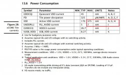
See please attached picture: if you stay at/under SR=192kHz, in case of XU208, I would recommend to consider about 380mA for 1V0, as the worst case.
As Lorien said, there are a lot of other apects you should take care of, too.
I like altor's solution, with TPS72010, even if it has a max. 350mA. Its main advantages are that it accept 1V1 as minimum input, it is cheap chip and it has good enough specs. I will try it in the future with pre-stage 5V0 to 1V2.
Meantime, waiting for TPS62912 (or TPS62913) back on stock.
Attachments
I use 1.8v pre-stage because I need it for other purposes.I like altor's solution, with TPS72010, even if it has a max. 350mA. Its main advantages are that it accept 1V1 as minimum input, it is cheap chip and it has good enough specs. I will try it in the future with pre-stage 5V0 to 1V2.
Even with the maximum regulator current of 350mA, power dissipation is (1.8-1)*0.35=0.28W, which is less than 0.615W allowed at +85C.
P.S. Also sometimes I use AP7365-10YG-13 in SOT89, as 1.0V regulator (no enable pin in this package!)
Last edited:
What is the reason for Vcore 1V0 to be linear, in a properly routed design?
I totally agree, PLL analog 1V0 should be very low noise linear, but it only requires a few mA.
I totally agree, PLL analog 1V0 should be very low noise linear, but it only requires a few mA.
In my designs I've always fed the 3045 with either 4V or 5V, depending on the needs of other LDOs present in the design.I think Dimitris didn't used 5V to directly feed LT3045 1V0, but he lowered the voltage first.
See please attached picture: if you stay at/under SR=192kHz, in case of XU208, I would recommend to consider about 380mA for 1V0, as the worst case.
As Lorien said, there are a lot of other apects you should take care of, too.
I like altor's solution, with TPS72010, even if it has a max. 350mA. Its main advantages are that it accept 1V1 as minimum input, it is cheap chip and it has good enough specs. I will try it in the future with pre-stage 5V0 to 1V2.
Meantime, waiting for TPS62912 (or TPS62913) back on stock.
I am using XUF208s and I don't think I've seen total power consumption going over about 350mA, so even in the case of going from 5V down to 1V we are talking about 1.4W of power, which can be relatively easily dissipated by a 4-layer PCB's ground plane.

Thank you Dimdim for clarification.
It depends on many other design specs. (i.e. ground plane surface, heatsinks, etc)
I've used it once with XU208, in a 4-layers too small surface PCB (Amanero size), but it wasn't feasable, so I had to glue a small aluminum heatsink on top of LT3045.
Another important design spec. is the power consumption of the other parts. In the example above I have used 2 pcs. of Si Labs SI545 oscs., which are very hungry (about 85-100 mA each, even in stand-by!). Anyway, i couldn't find any audible difference between XU208 with LT304x and my old XMOS U8 with Vcore dc-dc converter inside the chip.
@felipeunix
If you read LT3045 datasheet, you can find that for a 2500 square mm ground plane, the temperature will rise with 33-35 Celsius for every 1Watt.
That means that in case of 5cm x 5cm PCB, the chip junction temp. will rise to 1.4W x 34 = about 48 Celsius above the room temperature, let's say about 25 Celsius as the worst case, so you already have over 70 Celsius. If you consider the other parts heat disipation, or if LT is near the PCB edge, not in its center and also the situation when your project case will not be perfectly vented, you may find that your (entire, or a big part) XMOS board will run very hot. If this is acceptable for you, take care about choosing parts, especially capacitors.
Thanks everyone for the replies. 😃😃😃
@Thorp
According to the datasheet, the maximum consumption is 382mA(VDD+PLL), but I believe this is in projects with all cores active at full load, the typical consumption is reported as 175mA(VDD+PLL)only.
With the LT3045 working in 1v8 to 1v0, we have from 140mW to 306mW. I believe this is easily dissipated by MSOP12.
But this is just speculation, I haven't tested it yet, as soon as my parts arrive I'll put them to the test under these conditions and analyze the behavior.
**4v0 to 1v0 makes pcb design easier, but +500mW in typical consumption, doesn't seem like a good idea initially.
For 3v3 it doesn't specify the maximum, maybe because it's irrelevant... 50mA? Easy for any regulator.
To summarize my intention:
LT3045 - 1v8 to 1v0 (VDD+PLL)
LT3042 - 3v3 (VDDIO)
LT3042 - 3v3 (oscillators/mux/supervisor)
Sincerely? I don't believe in absurd differences. 🙃
But I don't know, as I haven't tested it yet.
@Thorp
According to the datasheet, the maximum consumption is 382mA(VDD+PLL), but I believe this is in projects with all cores active at full load, the typical consumption is reported as 175mA(VDD+PLL)only.
With the LT3045 working in 1v8 to 1v0, we have from 140mW to 306mW. I believe this is easily dissipated by MSOP12.
But this is just speculation, I haven't tested it yet, as soon as my parts arrive I'll put them to the test under these conditions and analyze the behavior.
**4v0 to 1v0 makes pcb design easier, but +500mW in typical consumption, doesn't seem like a good idea initially.
For 3v3 it doesn't specify the maximum, maybe because it's irrelevant... 50mA? Easy for any regulator.
To summarize my intention:
LT3045 - 1v8 to 1v0 (VDD+PLL)
LT3042 - 3v3 (VDDIO)
LT3042 - 3v3 (oscillators/mux/supervisor)
Exactly what I would like to know, the XS1 has a builtin switched regulator, in the 200 series the terminals are exposed, what is the reason? 🤔What is the reason for Vcore 1V0 to be linear, in a properly routed design?
I totally agree, PLL analog 1V0 should be very low noise linear, but it only requires a few mA.
Sincerely? I don't believe in absurd differences. 🙃
But I don't know, as I haven't tested it yet.
Here is another ten year user. Bought a V1.0 board in 2012. It has worked flawlessly in combination with a headless PC, Daphile software and Bufallo III DAC on a very picky home built 4-way hornsystem.
Thanks Lucian for 10 years High quality music
But I have a question: Is it possible to upgrade the firmware of the WAveIO and if yes, how to do it? I realise the WaveIO is 10 Years old and chances are thin the new firmware will fit the old board. In message nr. #1 Lorien describes how to do it, but before I do damage to a perfectly working board i first like to know it is possible.
Many thanks
Hi guys. As someone here works with XMOS maybe you have some ideas what is wrong with my xtag3 device. I cant connect to working board because the board is not detected. The situation is exactly the same as here described. Problem described
The diference that my xtag3 is new and is not working for the first time. I found some info that it can be related to windows system. I am using windows on parallels on mac. But other people i know sucsesfully using that way. Maybe someone had problem like this?
The diference that my xtag3 is new and is not working for the first time. I found some info that it can be related to windows system. I am using windows on parallels on mac. But other people i know sucsesfully using that way. Maybe someone had problem like this?
@henri47: sorry for my late reply. Too many things to do, too little time to do it 🙂
Since your board is v1.0 it may be possible that it doesn't have implemented the USB DFU (Device Firmware Upgrade) on it.
I say "may be possible" since I cannot be sure about that unless you're connecting your WaveIO card to any free USB port of your PC/host and check its serial number. If it's something like v0330 then it may need a new FLASH chip otherwise anything starting with v0331 has DFU implemented on it and you can safely update your board. From what I know, you can try to update the board regardless of the firmware version: if the DFU is not implemented then nothing will changing in FLASH memory; if the DFU is implemented and the instructions aren't followed accordingly then, again, all will stay the same.
Please PM me with instructions on how to find the serial number on WaveIO bards or if you need further advices regarding DFU implementation on your card.
@Baffless: I'm sorry that I'm not aware of this issue! I'm mostly using Xtag2 so I have no experience with this new adapter!
@tiggerkater55: well... welcome! (But for what? as my reply was too late to do you any good 🙂 Anyway I'm glad you figure it out!
Kind regards,
Lucian
Found the problem with xtag3 issue! Basicly two reasons developed problems. If someone will get problems as described above. Do like this:
Open xmos concole and run command Xrun -l
This fix the problem.
But only on native windows mashine. On mac or on win in virtal mashine this command did’t help.
Open xmos concole and run command Xrun -l
This fix the problem.
But only on native windows mashine. On mac or on win in virtal mashine this command did’t help.
- Home
- Source & Line
- Digital Line Level
- XMOS-based Asynchronous USB to I2S interface