How critical is it to surround R9 with the magnetic field of L1? I mounted all my resistors first and then noticed everyone has R9 going through the middle of L1. The leads on R9 have already been clipped, but I can always replace them.
If being in the middle of the field is not important, does the direction of the field have any effect? Do I need to try a clockwise vs counterclockwise coil orientation?
It’s a convenience. Don’t worry about it.
Using the calculator Pete linked to it gave for a 1uH 10mm diameter coil just over 14 turns. This then measures 2.2uH. So I don't know what gives but I shall use this as is. It looks the same as others I've seen on here!
Somehow I missed R10 30k on my Mouser order, I have some 27.4k laying around will these be ok to use?
From the schematic it looks like it is part of the mute circuit.
From the schematic it looks like it is part of the mute circuit.
It's gone a bit quiet on here this week so I thought I'd introduce myself just to try and bring this thread back to life.
I've been collecting parts to build this amp, which will be my first. I built a B1-K Nutube pre-amp last year which is still in daily use, so I'm not a total novice although I am slightly nervous about working with mains AC (B1-K has an SMPS). For this amp build I've sourced a pair of hand-wound Canterbury Windings 200VA 2x 20v secondary trafos and I'm planning to go fully dual-mono in a single case - it's going to be a bit of a beast in terms of size and weight.
Shout out to jimk04 who ordered up some boards for us both and is helping with other parts and general hand-holding. We have some spare boards if anyone needs.
Anyway, hi. Has anyone got any more build progress to share?
Just FYI...
I built a set completely w/o any of the components for the servo. I wanted to hear the chip w/o any influence from the opamp. I upped C2 to 330uF, C10 to 680pF, C1/C101/C201 to 2.2uF and by-passed the 220uF Panasonics with 440nF WIMAs. Other build components were changed but I have to create an orderly list (if anyone wants it) and it’s better you all build what is recommended first. DC offset was near zero. This little amp sounds fantastic! Bass & mid-bass are satisfying, with my pre-amp tone controls set almost to flat (I had to tweak the treble up a tad) I have wonderful airiness & soundstage. This is a great little lyrical chip-amp on par with any of the simpler LM3886 builds I’ve done. Dibya’s layout is well done. 7293 only slightly warms the heatsink (at my listening levels).
How’s everyone else’s builds going?
Cheers,
Pete
Here my build BOM for the servo-less build just for information sake..the R20 comment means the resistor type, not the value or its necessity.
Pete
Attachments
Last edited:
BOM is the bomb
Thanks Pete, really helpful.
What factors should help me decide whether or not to implement DC servo?
Thanks Pete, really helpful.
What factors should help me decide whether or not to implement DC servo?
I wish I could give you a definitive answer to that one. I had the luxury of building both and in my living room, on my speakers , and with my old ears, I preferred the non-servo one with the altered components.
The stock servo build sounds good as well; I will not write anything negative about it. I just wanted to hear the amp w/o having any op-amp & it’s circuitry in place. Luckily the DC offset was fine w/o it. The servo wasn’t just built-in just for the hell of it. Dibya had a purpose (obviously) and I have no scope measurements to justify the overall stability of my variation. But, nothing seems to overheat, the upper frequency is clear of audible distortion (as far as I can hear) and lower frequency response is satisfying.
It’s yours to gamble with. I’m glad the board design was robust.
Pete
Thanks Pete. Seems pretty complicated - I was hoping a simple LED would do, but maybe this is to give it some sort of hysteresis to make it easier to see.
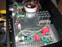
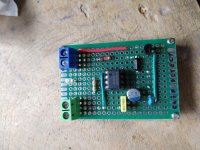
Ok X, so I went ahead and built the clip detector as suggested by AudioKiller (see schematic & my quick build below). The input voltage to the clip detect circuit was ~10VDC and the voltage regulator kept the circuit at ~5V. A wire soldered onto Pin 5 of the 7293 was then connected to the detect circuit. The voltage to the Xmas amp was +/- 25VDC after rectification. Speakers were NHT Super Zeros (8ohm). I played the music moderately loud and clipping was clearly detected by the circuit as the LED stayed lit for long enough to see the beginning levels of clipping. A very smooth visualization.
I then tried what you (and others have suggested): a simple resistor and LED setup. I used a Lite-On standard LED (LTL17KTBS3KS) and a 1K 1/2W resistor. The resistor was attached onto pin 5 on the 7293, the LED was attached to the resistor and then a wire from Pin 13 (from the 7293; 25V) fed the LED. I then played the music moderately loud again and clipping could be detected via the LED but visualizations were not as clear as with the clip circuit until the volume was increased (beginning levels of clipping were hard to see; very dim & very quick).
So the simple resistor & LED works and might be enough to see moderate levels of clipping. Lower levels maybe...just as long as it’s not a very bright room and you look intently at the LED.
Regards,
Pete
Attachments
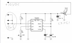
Thanks for sharing that. I think the 555 timer is being used as a mono stable vibrator to give some hysteresis and persistence so that our eyes can pick it up. It would be interesting to compare with and O-scope to see what is meant by clipping.
The clipping warning LED on a TPA3255 class D amp comes on when it detect moderate distortion at the peak. Not clipping quite yet and you get a faint flicker.
The clipping warning LED on a TPA3255 class D amp comes on when it detect moderate distortion at the peak. Not clipping quite yet and you get a faint flicker.
Thanks for sharing that. I think the 555 timer is being used as a mono stable vibrator to give some hysteresis and persistence so that our eyes can pick it up. It would be interesting to compare with and O-scope to see what is meant by clipping.
The clipping warning LED on a TPA3255 class D amp comes on when it detect moderate distortion at the peak. Not clipping quite yet and you get a faint flicker.
The sequel to this was that running the standard Xmas amp boards with more capacitance on each line (12000uF initially then increased to 24000uF per rail) enabled me to really crank the volume up before even getting a hint of the clip circuit to even show anything. Sitting 4-5 feet in front of the speakers I just couldn’t listen to the sound level I was driving the speakers before clipping occurred.
But you’re right, it could mean distortion instead of real clipping.
Nice work Pete as always.
Still not really got into this project yet but it will happen. I was building some LT4320 PSUS but have changed my mind on those.
And then I've discovered a thread on LM338 regulated supplies. Anyone considered that approach.?
I was thinking of going the capacitance multiplier approach but could always maybe add the 338s.
Last edited:
With a chip amp, it has very high PSRR that a quiet regulated supply is not an absolute must. Just 22,000uF per rail is enough. If you wanted you could do 9600uF and 0.22R and 22,000uF CRC and that would be even quieter.
The active bridge does make things quieter in the HF’s. Less diode switching noise. It also buys you 1.2v more on the rails as no diode dropout from a bridge.
The active bridge does make things quieter in the HF’s. Less diode switching noise. It also buys you 1.2v more on the rails as no diode dropout from a bridge.
Instead of 1k, try 220R and it should be 5x brighter and easier to see. The 555 acting as a mono stable vibrator and that extends the LED duration making it easier to see. But increasing brightness may be as easy as changing to a smaller LED.
I changed to a "super bright" white LED and it's pretty visible when you push the amp but one may miss the infrequent & short clips still. They are still easier to see with the 555 circuit but it's not like it's a wide region between clip (or whatever it really is) onset versus having the LED well lit.
Pete
Pete
I think I have re-read the entire thread, and I thought I only saw two references to what power the amp puts out, 30 watts at 8 ohms with the servo, and 100 watts with no servo.
If building it with the servo, do you really need a 300VA 25v x 2 transformer?
Is 25v x 2 fine for 4 ohm speakers?
If building it with the servo, do you really need a 300VA 25v x 2 transformer?
Is 25v x 2 fine for 4 ohm speakers?
As pointed out before, the servo circuit itself isn't responsible for lower ouput power. It's the voltage regulators with their limited input voltage. You can circumvent this by applying zener diodes and a ballast resistor instead.
Best regards!
Best regards!
- Home
- Amplifiers
- Chip Amps
- Xmas Amp - Dibya's TDA7293 by Jhofland