Pete sorry
I didn't see this reply. My system doesn't lack bass for my tastes so I shall try my 2.2 PP.
About C16. It is in the signal path but I see a lot using polar caps. I take it we don't need bipolar here. ? I have 100uf Gold tune or Muse ES. My small knowledge tells me polars won't like the sine wave audio signal. Can someone briefly clear that up for me?
Thanks
Looking forward to completing this but not quite htere yet.!Also why are J1 and 3 as they are. Why not use 2 pin and 3 pin connectors?
jimk04: there should be no reason one can’t use a non-polar at C16 but I will stand corrected if the sine wave audio signal disruption is said to be a real thing. C16 is by-passed with a 100nF non-polar already as part of the normal build.
I know X used these same two board connectors in his 3255 Class D amp and I thought they were a bit much at first but…..having double the solder joints and the plastic locking pin insert really leads to a solid connection for both power in and music out (typically larger gauge wiring). Disconnection is fast and Connection is really secure. I grew to like them, but yes, they are more than needed. You can just solder the wires directly into the solder holes if you want or use any other connector you have on hand that fits.
Pete
I even use those Molex Minifit 4 pin connectors for critical flying leads to remote mounted power MOSFETs outputs. Use silicone insulation RC race car wires. They conduct more amps and stay soft and temp resistant. This lets one pull an amp board out of a chassis in 30 seconds. Leaving behind the output power MOSFETs or power BJTs secured to heatsink.
Is there ever a problem with too much capacitance?
I have four Cornell Dubilier 380LX153M050A042 Aluminum Electrolytic Capacitors - Snap In 15000uF 50V 20% that I was going to use with a 300va 24v transformer.
Cornell Dubilier 380LX153M050A042 Aluminum Electrolytic Capacitors - Snap In 15000uF 50V
I have four Cornell Dubilier 380LX153M050A042 Aluminum Electrolytic Capacitors - Snap In 15000uF 50V 20% that I was going to use with a 300va 24v transformer.
Cornell Dubilier 380LX153M050A042 Aluminum Electrolytic Capacitors - Snap In 15000uF 50V
For a Class AB amp, it’s not a big problem other than causing a large in rush at turn on. You will need some more soft start precautions. For a Class A amp that flows continuously high current levels, too large of a capacitance will cause higher ripple currents with the charge/discharge cycles. This can heat and cause caps to fail prematurely. The ripple current rating of the cap needs to be matched. Preferably about 2x higher than the rms ripple current of the first cap of the CRC PSU. This needs to be simulated to estimate the operational ripple current. People who think more is better and have these monster 200,000 uF cap banks are in addition to wasting money, making their amps not work as well and hurting it’s lifetime.
With that said, for the Xmas amp, PSU with 15,000uF is fine.
With that said, for the Xmas amp, PSU with 15,000uF is fine.
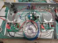
I started on the Xmas amp a couple of day ago, here is my progress so far,
If you see anything wrong, please let me know!


First time making an inductor, what a PITA.
Not 100% sure on the connectors yet, so I didn't solder anything on the board yet.
Next up is a Prasi power supply.
David.
If you see anything wrong, please let me know!
First time making an inductor, what a PITA.
Not 100% sure on the connectors yet, so I didn't solder anything on the board yet.
Next up is a Prasi power supply.
David.
Yes, very good idea to make 100% sure before switching on the power. Very neat and colorful boards David.Not 100% sure on the connectors yet, so I didn't solder anything on the board yet.
I managed to get something wrong and blew up my amp in a second. The TDA chips popped like firecrackers and went up in smoke. Coined a new acronym – SOB
 – smoke on the bench. Could also be called karma - since I was making fun of other members.
I gave mine ±32V DC for a few seconds, but probably in the wrong way and without safety goggles.There you go Vunce – a simple way to test how authentic your V6 Mouser chips (and mine in the shopping cart) are – please give them more than ±25V DC. Just wear safety goggles when doing this. 🙂
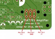
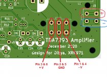
So, just to confirm the J1 Molex pinouts and match with the schematic. Is this correct?
Attachments
Sorry to hear but I think you got pos and neg wrong way round. See how left pin connects via small tabs to the plane that feed the - side of the cap in your picture
Yes thank you - you are correct and my drawing is totally incorrect.
Now you all know how to pop an authentic TDA chip. Don't do this at home.
Now you all know how to pop an authentic TDA chip. Don't do this at home.
Here is how mine is connected. Red is positive, black is GND, white is negative. Seems to match what you have there Twocents. You can see that the positive pin of the rail smoothing cap is connected to the left pin.
Yes, very good idea to make 100% sure before switching on the power. Very neat and colorful boards David.
I managed to get something wrong and blew up my amp in a second. The TDA chips popped like firecrackers and went up in smoke. Coined a new acronym – SOB
I gave mine ±32V DC for a few seconds, but probably in the wrong way and without safety goggles.
So, just to confirm the J1 Molex pinouts and match with the schematic. Is this correct?
Your pinnings are correct ..L-to-R: +V GND -V
The speaker connections are as shown:
You made sure your 7293’s weren’t grounded to the heatsink, correct?
Pete
Attachments
Last edited:
If you folks don’t have a light bulb circuit to test for shorts when first powering up anything new you’ve built, Google it and make one. It will save you lots of grief after hours of soldering. Just remember the light bulb tester will always briefly light up when powering up a robust transformer + PS (caps are charging). If the lamp is glowing brightly pull the plug ASAP.
Cheers,
Pete
Cheers,
Pete
Xmas amp test chassis
Hi everyone!
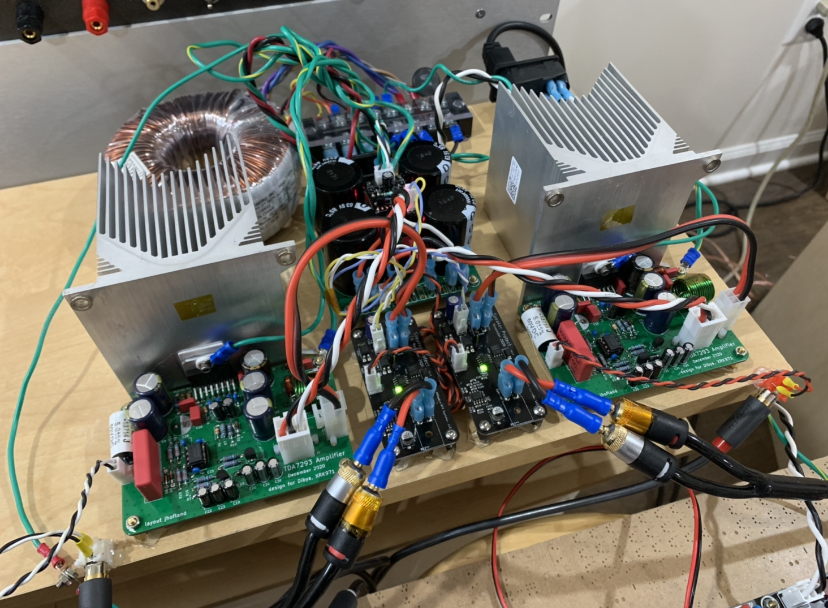
I built the amp a few months ago and had it it my rather sloppy (and well ventilated) test chassis. Despite flying leads everywhere and an open air layout, this amp is dead quiet! I listened to it for 6 or more hours a day for 8 weeks and have to say I am truly impressed!
I did make one change though. While I thought the amp sounded wonderful I felt it needed just just a little more punch as I was listening to it in a rather large room so I swapped out R-3 from 750R down to 680R thus boosting the gain a bit. I was worried that it might negatively
effect the fidelity of the amp but I'm pleased to report that it did not. The slight boost in horsepower gave it a noticeable increase in slam that was just what it needed for my application.
Hats off to everyone involved in the design & production of the boards and a special thank you to Dibya for giving this project to the DIY community. Well done! I ran this amp hard at time & it never failed to impress!
Here's a pic in the test chassis. I can't wait to get it in a proper box but first I have to finish another project I have going. I think I'm going to give the Xmas amp to my grandson for his upcoming 16th birthday. Thanks again to everyone for making this possible!
Almost forgot...I'm running the amp at +/- 35V and it didn't go boom!
Jim
Hi everyone!
I built the amp a few months ago and had it it my rather sloppy (and well ventilated) test chassis. Despite flying leads everywhere and an open air layout, this amp is dead quiet! I listened to it for 6 or more hours a day for 8 weeks and have to say I am truly impressed!
I did make one change though. While I thought the amp sounded wonderful I felt it needed just just a little more punch as I was listening to it in a rather large room so I swapped out R-3 from 750R down to 680R thus boosting the gain a bit. I was worried that it might negatively
effect the fidelity of the amp but I'm pleased to report that it did not. The slight boost in horsepower gave it a noticeable increase in slam that was just what it needed for my application.
Hats off to everyone involved in the design & production of the boards and a special thank you to Dibya for giving this project to the DIY community. Well done! I ran this amp hard at time & it never failed to impress!
Here's a pic in the test chassis. I can't wait to get it in a proper box but first I have to finish another project I have going. I think I'm going to give the Xmas amp to my grandson for his upcoming 16th birthday. Thanks again to everyone for making this possible!
Almost forgot...I'm running the amp at +/- 35V and it didn't go boom!
Jim
Attachments
Well done legis31! Enjoy your build.
Me thinks the large heatsinks may be a bit more than you need but they are cool looking..;>)
Pete
Me thinks the large heatsinks may be a bit more than you need but they are cool looking..;>)
Pete
- Home
- Amplifiers
- Chip Amps
- Xmas Amp - Dibya's TDA7293 by Jhofland