Nice heatsinks Legis! I think if you run the amp hard, they are the right size for natural convection. They are designed for use with a fan and as such can handle 100w plus.
I think I got mine for around $7 to $10ea. Could not pass them up and have like 6 pairs.
Search eBay for:
“Dell Precision Workstation T3500 T5500 T7500 CPU Heatsink T021F 0T021F”
In EU, I assume there is a similar site for surplus electronics like eBay?
I think I got mine for around $7 to $10ea. Could not pass them up and have like 6 pairs.
Search eBay for:
“Dell Precision Workstation T3500 T5500 T7500 CPU Heatsink T021F 0T021F”
In EU, I assume there is a similar site for surplus electronics like eBay?
Last edited:
Thanks for the info xrk!
As far as I know the fan is not directly attached to the heatsink, more like an air tunnel to force the air going through the fins.
As far as I know the fan is not directly attached to the heatsink, more like an air tunnel to force the air going through the fins.
Ahhh...that explains things. Since these heatsinks were originally used with a CPU I assumed the fan was mounted directly.
Getting ready to do a build on this. I was looking for a simple figured out chip amp to build, and this fit the bill, thanks to the developers.
I've started collecting parts.
JLCPCB sent me 5 boards,
antek sent a 3225 dual 25v secondary 300va transformer,
Ampslab.com supplied 5 tda7293 chips,
Power Supply will be my own design PCB with 48,000uf of capacitance.
Case is on the way on the slow bus from China. Case is 320mm*300mm, so nice and compact.
Gotta decide what to do for protection. I also have a diyaudio soft start board floating around I might use.
Plan is to use this in the kitchen, or the bedroom, somewhere. I like my little polk rt25i speakers in my office, so maybe I'll try it there.
I'll post again when I get down the road a ways on the build.
Attachments


Hey Summitp,
the pics look good. I'm interested in how your build goes and how it works when it's done. 48000µF sound good. Is it per rail or all together? Dual 25V/300VA is perfect 🙂.
I just put 5 PCB's in my shopping cart at JLCPCB. I already use two TDA7293 paralleld for my Subwoofer, but I'm interested how a single one compares to the open source LM3886.
Hi Summitp,
Nice work on gathering the parts. You are using a single Antek 3225 for both channels correct? Probably 20,000uF PDT rail is enough or 48,000uF total both rails as you state.
These chip amps need speaker protection from what I have heard. They can fail and put full DC rail onto your speakers.
I use a solid state relay protection with delay turn on for anti thump and instant turn off for anti thump power down.
Yes, the power supply will be shared by both channels with 48,000 if total capacitance. I have these power supply boards laying around, first pcb I designed (one is already working quite well with my gb150d amp) and I want to try it out in a chip amp. Thanks for the design! I'll figure out a protection scheme. I saw some boards that attach right to the speaker terminals on the back of the case, that looked cool, and Gerber's are available. We'll see.
Nice work SL.
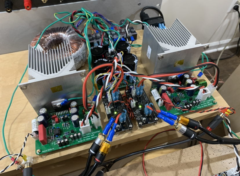
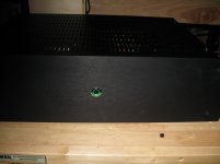
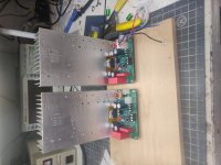
Made. Alittle progress on mine. Unfortunately the case was delivered to Chihuahua Mexico. I am not in Chihuahua. A little digging turned up an appropriate size piece of wood and a couple heatsinks from a dead Yamaha reciever.
I forgot to order the 2.2r 2 watt resistors for the zobel network. I did have some 2.2r 1 watt. Is that going to be a problem? Only if I play it really loud and it starts oscillating right? My other "in stock" option is paralleling a couple 10r 2W to make a 5r resistor.
Just gonna get a test setup going until a case shows up.
Edit, grrr why is my photo flipped on the side ...
Attachments
Nice work, Signal Lost! Glad it’s working out for you. Very neat build. What did you use for the speaker protection circuit?
That’s an interesting PSU board - are those LED bar graphs near the screw terminals?
That’s an interesting PSU board - are those LED bar graphs near the screw terminals?
Thank you for the comments X.
Yes those are bar graphs on the power supply. It is this one from parts express.
I have been trying to complete the many projects I have started using the stuff I have laying about. The speaker protection board is the Velleman K4700. Seems like most projects get slowed down by over-thinking what you need to make it work. I am trying to just build all the projects I have the parts for and use them or give them away. Better for them to be playing music and making some one happy then collecting dust. Maybe next project to get done is that Aska Lender pre-amp board set collecting dust.
Signal, what is the power control board you are using? Has a soft start, and provides other voltages for your protection board? Also allow use of a low voltage power switch to connect the transformer?
Summitp it is Mark Johnson's soft start board described in this thread
It is a great design and really useful. The speaker protection board has its own PS so it connects to the mains voltage at the soft start board. The SS board allows a low voltage switch, on LED, off LED and has a low voltage output for other boards like remote control. All your questions can be answered in the first post of the linked thread. Mark did a comprehensive design of that board and I recommend you build one.
Misspelled the pre amp board in the previous post should be Aksa Lender. Apologies
Summitp it is Mark Johnson's soft start board described in this thread
It is a great design and really useful. The speaker protection board has its own PS so it connects to the mains voltage at the soft start board. The SS board allows a low voltage switch, on LED, off LED and has a low voltage output for other boards like remote control. All your questions can be answered in the first post of the linked thread. Mark did a comprehensive design of that board and I recommend you build one.
Misspelled the pre amp board in the previous post should be Aksa Lender. Apologies
What is the VA of your transformer? Was it large enough to need a soft start? That seems like a lot of board if it is only being used as a low voltage start.
Hey DaveFred
If you read Mark's thread about the genesis of the board it was to solve the problem of reaching behind an amp to switch it on. He did a thoughtful design that would be easy to build and use and (to me) difficult to misuse. Then he gave it away. So it is a lot of board but it is a board to use a low voltage switch
Do I need it? unknown, but it has allowed me to use the switch I had. The amp ended up looking good, may have a greater margin of safety and I gained experience with the board to eventually use it on an F5, F6 or MX2. But you should read the post about the board.
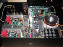
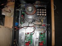
I am at the point where holes need to be drilled in the case and everything is about to be mounted.
Anything wrong with how I have this laid out?


Power will entering at the rear bottom left (looking from the front).
RCA's will be entering near the ALPS 10K pot. Oversized volume knob will be on the front with a brass rod connected to the ALPS pot at the rear of the amp.
Speaker posts will be to the left and right of the protect board that's in the middle.
Is it a bad idea to run the 110v from the input at the back of the case underneath one of the amp boards to the toroidal transformer? Would there be an advantage to putting a metal plate between the 110v wiring and the board?
What about shielding the toroidal transformer itself, Putting a metal box around it, inside the case? I don't see this very often. If it falls under the heading of, "cannot hurt", I don't want to do it because of the amount of effort involved, but if it is correcting the source of a major problem I will.
Any other comments about the layout?
Thank you,
David.
Anything wrong with how I have this laid out?
Power will entering at the rear bottom left (looking from the front).
RCA's will be entering near the ALPS 10K pot. Oversized volume knob will be on the front with a brass rod connected to the ALPS pot at the rear of the amp.
Speaker posts will be to the left and right of the protect board that's in the middle.
Is it a bad idea to run the 110v from the input at the back of the case underneath one of the amp boards to the toroidal transformer? Would there be an advantage to putting a metal plate between the 110v wiring and the board?
What about shielding the toroidal transformer itself, Putting a metal box around it, inside the case? I don't see this very often. If it falls under the heading of, "cannot hurt", I don't want to do it because of the amount of effort involved, but if it is correcting the source of a major problem I will.
Any other comments about the layout?
Thank you,
David.
I would move the power trafo away by mounting it on its side using a L bracket. Move the speaker protect board to the rear panel and let the AC mains run in middle of case away from amp PCBs. Place PSU board on floor in middle in between the amps. If you move the trafo father away I don’t think you need shielding. Sheet steel box works. Or get mu metal shielding foil. But try it first loosely mounted (or held in place with blue tack) etc to listen to the noise. Adjust orientation for best case. Rotation of transformer can have an effect.
To make room, you can bend the pins of the chips so that it mounts on same plane as PCB like an underhung active. Mount amp PCB and chip amp on the heatsink side panel. That will open up all sorts of space inside the cramped chassis.
To make room, you can bend the pins of the chips so that it mounts on same plane as PCB like an underhung active. Mount amp PCB and chip amp on the heatsink side panel. That will open up all sorts of space inside the cramped chassis.
Last edited:
- Home
- Amplifiers
- Chip Amps
- Xmas Amp - Dibya's TDA7293 by Jhofland