Thanks for sharing the details. Do you know how many volts this outputs?
As shown by the values used during testing, a 3.1V RMS drive level from the amp is typical for "comfortably loud" listening, with peaks of twice that. The transformers (2 in series) are 50:1 stepup (measured). So 3.1VRMS = 8.7VP-P x 50 = 430V driving the phones.
I often use microwave oven transformers as inductive loads for SE Class A amps. It doubles the voltage swing.
Clever!
I never use the secondary HV windings - they are left unconnected. They are designed to make 2500v from 120v. I wonder if I tapped into them I could get a nice transformer coupled Class A electrostatic headphone amp! They sure are quiet.
I don't have personal experience with true externally-biased electrostats, but from what I've seen/heard they use HV amps and not transformers. Only the electrets seem to use xfmrs.
Well, HV is HV and it just depends on the way you make it I think. But I am no expert on electrostatic headphones. Nice thing with transformers is that the voltages in the amp PCB are reasonable and normal. It’s a whole different ballgame to deal with 500v in PCB traces.
I have seen similar Fontek Headphones in our closet, those were used by my grandfather. I always wonder where is his headphone amp, May be he use to plug them to his Philips HiFi amplifier. Isn't that noisy? I mean that Philips is definitely way noisier than 7293.
I have seen similar Fontek Headphones in our closet, those were used by my grandfather. I always wonder where is his headphone amp, May be he use to plug them to his Philips HiFi amplifier. Isn't that noisy? I mean that Philips is definitely way noisier than 7293.
AFAIK, Fontek only made two or three different models, and I'm pretty sure they were all electrets. So a stepup transformer box like the one in my pic is needed, a hifi amplifier isn't going to drive them. Post (or PM me) a photo of the headphone's plug, that will tell the story.
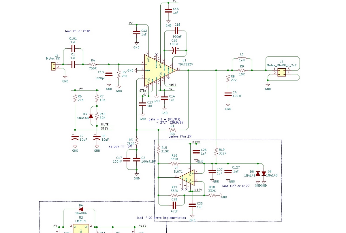
The DC servo is ... to allow the elimination of the feedback shunt capacitor. This improves the imaging because there is no phase dependence from the cap on the feedback loop. It is DC coupled as C2 is replaced with a jumper.
I think you meant phase shift, not phase dependence.
With 20k / 1k Ohms feedback resistors and 100uF feedback shunt cap, the response is -3dB @ 1.59 Hz. Phase shift is 4º at 20Hz, 1º at 100Hz. DC offset is -3.5mV.
Eliminating the 100uf C results in a DC offset of -4.9mV. I've monitored it for half an hour and it hasn't changed. This is insignificantly different from what the servo accomplishes. The servo appear to solve a problem that doesn't exist. I'm removing the cap.
In the stock setup with 750R series R and 20k shunt R, the 220pF input filter capacitor C10 results in -3dB at 1MHz. I would suggest doubling the size of that cap (halving the freq) to clean up the falling edge of the amp square wave response. I have mine at 400kHz.
Yes. I meant phase shift. It’s significant in the sense that it’s very audible if one amp has the cap and another amp doesn’t have it. The stereo image is all messed up and you get a “phasiness” sense of brain fatigue and a headache.
Well there's no phasiness or fatigue here. This is a really nice sounding amp.  In a whole different class than the LM1875-based amps I built last month.
I've been listening to a variety of music I know well and it renders them all really well. Smooth and detailed in the mids where it counts. Good depth when it's present in the recording. I've learned not to judge the upper octave or two at night, when my ears are less sensitive, but I hear nothing up there that raises any flags. It may be just a tad lightweight on the bottom but I'm not sure of that yet. I'm going to make lower-impedance ground wires from the power supply tomorrow, it's just an 18 gauge, the same as the rails, at present. I think I have some 16 gauge Litz tucked away somewhere, that might be interesting.
BTW, this is all with a +-15 volt @1A Power One modular linear supply.
I'm throwing over 20dB of signal away with the trim pots. It's a shame. I don't need at this gain. I'm tempted to dial it back a couple dB at a time and check for stability. We'll see.
At comfortably loud listening levels, the heatsinks are just warm to touch, not even hot.
Overall, I'm very impressed. This is the first really good chipamp I've heard. You guys did a great job on it.

In a whole different class than the LM1875-based amps I built last month.I've been listening to a variety of music I know well and it renders them all really well. Smooth and detailed in the mids where it counts. Good depth when it's present in the recording. I've learned not to judge the upper octave or two at night, when my ears are less sensitive, but I hear nothing up there that raises any flags. It may be just a tad lightweight on the bottom but I'm not sure of that yet. I'm going to make lower-impedance ground wires from the power supply tomorrow, it's just an 18 gauge, the same as the rails, at present. I think I have some 16 gauge Litz tucked away somewhere, that might be interesting.
BTW, this is all with a +-15 volt @1A Power One modular linear supply.
I'm throwing over 20dB of signal away with the trim pots. It's a shame. I don't need at this gain. I'm tempted to dial it back a couple dB at a time and check for stability. We'll see.
At comfortably loud listening levels, the heatsinks are just warm to touch, not even hot.
Overall, I'm very impressed. This is the first really good chipamp I've heard. You guys did a great job on it.
Hi Jbau,
Thanks for letting us know how it is working out. Glad you like it. It is indeed a nice sounding amp. Please show us a photo of the setup when you get a chance.
Thanks for letting us know how it is working out. Glad you like it. It is indeed a nice sounding amp. Please show us a photo of the setup when you get a chance.
Will do. The setup will remain in a temporary state for the next week or so. I'm also putting together some LM3886-based boards, and will use the same power supply to test them. I won't clog your thread with the comparison...
I worked on cleaning up the transient response today. There is a lot of overshoot at low levels that goes away at higher voltages. I saved the measurement binaries but forgot to make JPGs of them. Will do so manana and post them.
But the results are: For the 750R / 20k input and feedback setup you used, I highly recommend changing the input rf filter capacitor C10 to 470pF, and adding a 10pF C0G or NP0 across the feedback resistor R1. This eliminates the overshoot, makes + and - slewing more symmetrical, and opens up soundstage detail nicely.
Thanks for the tips on adding a 10pF cap across R1. I think I have a silver mica that might work nicely there. One can also change the input resistor R4 to 1k5 to decrease the RF low pass filter frequency. Although, that may attenuate the input signal.
Silver mica is good, too. Better to leave R3 and R4 the same to maintain the impedance balance, and change C10 instead. C10 and the feedback cap across R1 work togther to define the transient behavior. You don't want them tuned to the same cutoff frequency...
Last edited:
Yup, singing away🙂
I was going back in to increase increase C1 anyway. But, I won’t do that until after these tweaks.
I was going back in to increase increase C1 anyway. But, I won’t do that until after these tweaks.
Quote:
In the stock setup with 750R series R and 20k shunt R, the 220pF input filter capacitor C10 results in -3dB at 1MHz.
Hmm, well spotted, that's indeed very high, I would have rather expected anything between 150kHz and 400kHz.
It is a pity we don't have Dibya's oscillation results with the various PS caps. I believe I read somewhere it was very high frequency. I wonder if the reason isn't that input filter that is set too high and possibly catching HF through the board inputs etc.
By going at the input for a low pass filter with say Fc= 400kHz as suggested by jbau, I can't help wondering if the PS oscillations one would have with 1000uF and 0.1uF PS caps would still be there or not.
If not, that could open a new door to experiments with PS bypass caps and possibly enhence or tailorize further the sound of this well born amp.
Just thinking out loud
Claude
Back in the 80's-90's we ran into this same problem with many opamps with AB output stages and unity-gain freqs of 4-8 MHz. The LM1875 I played with last month has the same problem.
A curious omission from the TDA7293 data sheet is an open-loop gain-phase response curve. If they'd included that graph, we would have been able to make a good guess of what freq to tune the feedback compensation cap for, so as not to have our gain curve cross the open-loop response curve if the phase at that gain is less than 60º. It's like crossing the neutral zone.
The resonance I saw was ~1.3MHz. It's not really a PS-caused issue, but optimum PS bypass cap to help control it would be a little less than 1uF, in the 680n to 820nF region.
The technique I learned is to increase the compensation cap until there's no falling-edge overshoot at low levels (undershoot is OK), then set the input filter cap well below that so as not to excite the resonance.
This problem gets swamped at higher voltage excursions, which is probably why the chipamp mfr's don't put feedback comp caps in their recommended setup. Instead, they just spec the minimum gain high enough to avoid the issue.
I am now more optimistic that I can reduce the amp gain by 6-10dB and keep it stable.
Very intersting and in line with a comment I had about a resonnance at 1.5MHz or so.
I shall be very interested in reading you on how to tackle this problem, as it is beyond my reach. If you can succeed resolving that issue then it may well open some new fields of sound tweaking investigation around this well born unit.
IMHO, having 28dB gain is fine unless one needs to get really lower, but obviously you need then to know what you are doing as getting into the grey zone. Having a LPF at the input with a Fc between 100kHz and 200KHz is IMHO very acceptable aswell.
Question is: what is needed in the FB loop to get this tricky chip stable?
An additional question could also be: apprently we know we can cure part of the problem with a 1uF cap + 220uF cap in the PS, but is there a possibility to cure the problem differently? Or in a way to ensure we can play with PS bypass caps having a larger fied of choice (say covering a range of bypasses from 0.1uF to 1500uF, even if we have to stick to that 1uF one aswell). The reasoning behind is not being forced to stick to given PS caps because of the resonnance problem, but to be able to chose (or add worst case) bypass caps only by sonic qualities.
Very interesting...
Claude
- Home
- Amplifiers
- Chip Amps
- Xmas Amp - Dibya's TDA7293 by Jhofland