Hi X,
Well, I was a bit confused by Dibya's comments re PS bypasses, hence asking.
I was pondering he possibility of replacing the 220uF caps by 1000uF low ESR caps. Of course no one can tell if it sounds better, but then at least I want to make sure you guys didn't detect something odd re oscillation (?), see post above. A nice cap that has the same diameter as the 220uF could be Panasonic's EEU-FS1H102L. For sure at least a positive re reserve and damping factor in the bass region for the woofer.
Further, just for information, to balance things, I was pondering replacing the 1uF X5R with a similar footprint 2.2uF X7R... and a 0.082 C0G (underboard for example).
So at the end, after the remote main PS caps with say15000uF, on the board the PS bypasses would consist per voltage line of:
2x1000uF low ESR + 2x2.2uF X7R + 2x 0.082uF C0G.
That is instead of the proposed 2x 220uF + 2x 1uF X5R
POV?
Just thinking out loud...
Claude
Just put 1000uf Electrolyte and 0.1uf close to pin , most newer production 7293 will oscillate around 10Mhz for sure as they have higher slew rate than old production one , as consequence you will have blurred midrange and headache after listening.
You can go ahead with 2x2.2uF X7R + 2x 0.082uF C0G. (may give better sound).
ST datasheet are written by Engineers when they are drunk. ( Kudos to them for amazing ic)
Any way Chip amp shall remain Cheap!
You can go ahead with 2x2.2uF X7R + 2x 0.082uF C0G. (may give better sound).
ST datasheet are written by Engineers when they are drunk. ( Kudos to them for amazing ic)
Any way Chip amp shall remain Cheap!
Last edited:
Just put 1000uf Electrolyte and 0.1uf close to pin , most newer production 7293 will oscillate around 10Mhz for sure as they have higher slew rate than old production one , as consequence you will have blurred midrange and headache after listening.
You can go ahead with 2x2.2uF X7R + 2x 0.082uF C0G. (may give better sound).
ST datasheet are written by Engineers when they are drunk.
Any way Chip amp shall remain Cheap!
Hi Dibya, so just to clarify your suggestion, if we decide to replace the 220s with 1000uF electrolytics, we should solder the 0.1uF caps directly onto the leads of the 1000uf caps? The extra option is to replace C12-15 with 2.2uF X7Rs+0.082uF C0Gs?
Thanks,
Pete
I tested the Xmas amp with a SSR DC protect and it works well - absolutely silent turn on and off process. Cannot tell the amp is switched on or off unless music was playing. The amp sounds great. Playing with my RS225/10F FAST TL speakers at present.
I built one amp w/ 26dB gain and no servo and tested it tonight. It powers up briefly but quickly draws too much current and my ps goes into shutdown. Only running +-15V rails for now. Can't find any shorts or wrongly-placed components. Grrr.
I'm using 470uF/35V low-ESR lytics for C5, 6, 9,and 11. Could that possibly be the problem? I just read that Dibya sez not to use anything larger than 220uF. If so, I've never seen an amp oscillate from too much capacitance on its rails.
I'm using 470uF/35V low-ESR lytics for C5, 6, 9,and 11. Could that possibly be the problem? I just read that Dibya sez not to use anything larger than 220uF. If so, I've never seen an amp oscillate from too much capacitance on its rails.
Last edited:
Never mind, C4 of the Zobel is labelled C3 on my board and hence was empty. This thing oscillates without the Zobel in place!
Tomorrow, it's bed time.
I also found an intermittent ground connection on my input lead that was being a good antenna.
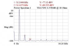
Here's 1kHz distortion at 1/2 the maximum level into the load I'll be using it at (driving electrostatic headphones). This setup measures very clean, all harmonics except the 2nd are basically in the analyzer noise floor. -87dB= ~0.004%. This is a better result than the LM3886 I'm also building. Impressive early results!
DC offset also very low, even with a 10k input pot and no servo...
I also found an intermittent ground connection on my input lead that was being a good antenna.
Here's 1kHz distortion at 1/2 the maximum level into the load I'll be using it at (driving electrostatic headphones). This setup measures very clean, all harmonics except the 2nd are basically in the analyzer noise floor. -87dB= ~0.004%. This is a better result than the LM3886 I'm also building. Impressive early results!
DC offset also very low, even with a 10k input pot and no servo...
Attachments
Last edited:
Hi Jbau,
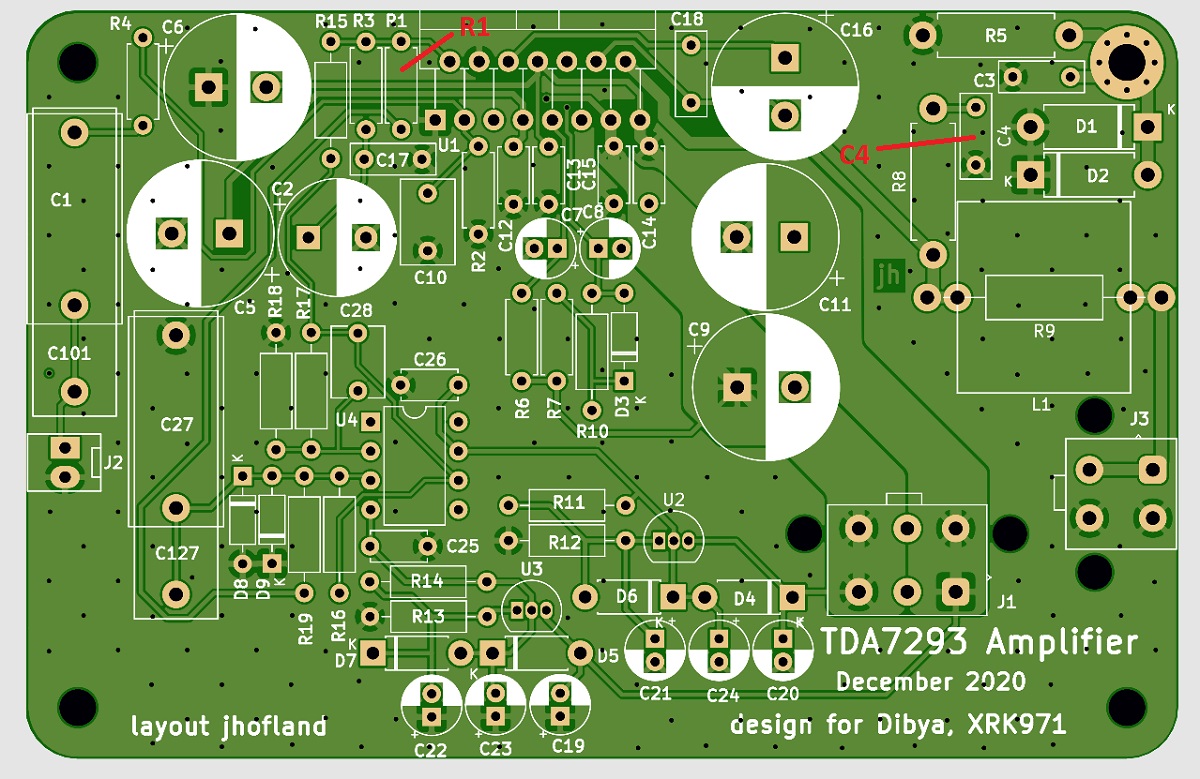
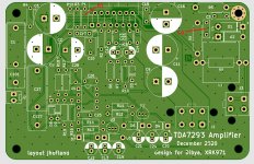
Sorry you had some startup issues - I assume they are all resolved as you now have measurements? C4 is the Zobel cap and must be in place as you found out. Some switch mode PSU's do not like to see a large cap bank upon startup. There are exceptions - like the superb ones by Cresnet (Micro-Audio) they do not have any issues driving 40,000uF upon startup. Some of the silkscreen is unfortunately, obscured by vias. Most notably, R1 looks like "P1". Please let us know how the amp is working now. You will drive headphones with it? Wow, didn't know that was a possible use case even.
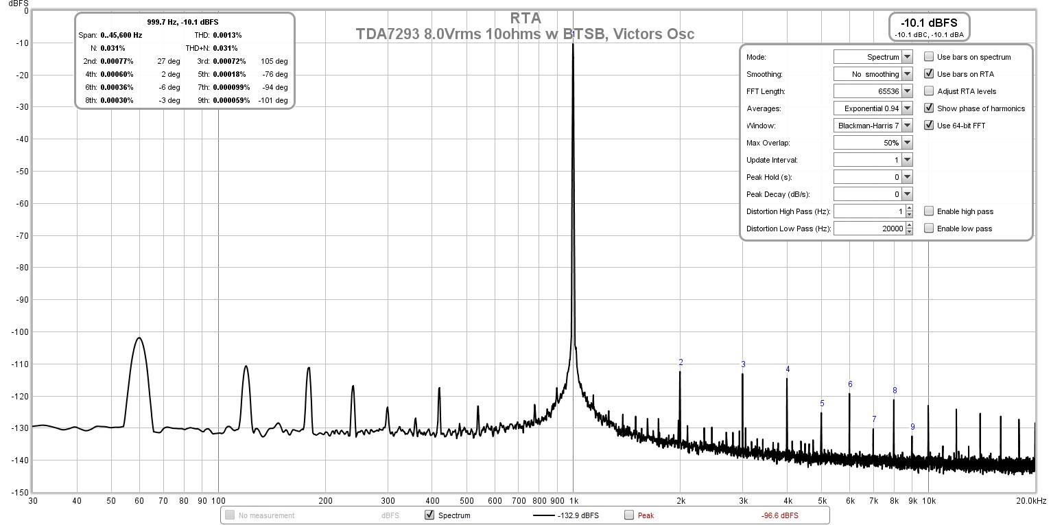
Your measurements look promising but limited by your audio interface I think. I measured -102dB distortion at 8Vrms into 10ohms:
Sorry you had some startup issues - I assume they are all resolved as you now have measurements? C4 is the Zobel cap and must be in place as you found out. Some switch mode PSU's do not like to see a large cap bank upon startup. There are exceptions - like the superb ones by Cresnet (Micro-Audio) they do not have any issues driving 40,000uF upon startup. Some of the silkscreen is unfortunately, obscured by vias. Most notably, R1 looks like "P1". Please let us know how the amp is working now. You will drive headphones with it? Wow, didn't know that was a possible use case even.
Your measurements look promising but limited by your audio interface I think. I measured -102dB distortion at 8Vrms into 10ohms:
Attachments
Last edited:
Thanks xrk, my problems were both errors on my end. I misread the silkscreen and loaded C4 into C3 position - hence no Zobel. This chip needs the Zobel for stability.
My measurement system is 16-bit (HP 3565S) so it may not resolve -102dB harmonics. With averaging, the noise floor is about -105. Because I'm using a pot on the input, upsetting the impedance balance, I expect to give up some THD as a result. No way to avoid that, unfortunately. No worries - any amp with HD that measures near -90dBr is bound to sound pretty good - I think I can "suffer" with it! 🙂
I'm also happy to see DC offset well-behaved without the servo. If the other board does as well, I'll probably leave it off.
Last edited:
Can you post a pic of your built amp board?
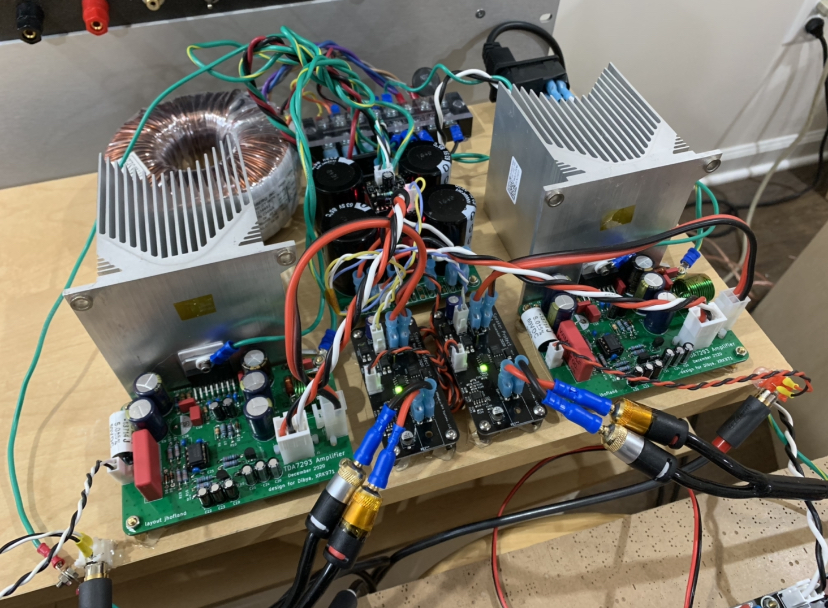
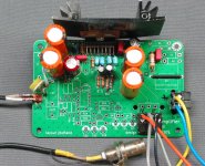
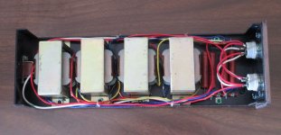
Here it is, configured for testing. Once everything is finalized, the trim pot will be replaced by a panel mount one, the connectors will be removed, and all connections soldered to the board. No Molexes!
BTW, even this heat sink is about twice the size actually needed for my application...
Attachments
The DC servo is actually not to keep the offset near zero (not the primary purpose), but to allow the elimination of the feedback shunt capacitor. This improves the imaging because there is no phase dependence from the cap on the feedback loop. It is DC coupled as C2 is replaced with a jumper.
You should consider keeping the output Thiele network to ensure stability into a capacitive load.
You should consider keeping the output Thiele network to ensure stability into a capacitive load.
Last edited:
Two sides of the same coin, really. I'll evaluate the LF response before committing. The LM1875 amp I built did not use the feedback C and the offset was only a few mV.
The load is not capacitive, it is 18" of wire into the coupling transformers for the headphones.
The load is not capacitive, it is 18" of wire into the coupling transformers for the headphones.
You are probably fine as you are driving a big inductive load. Maybe a series resistance of about 2ohms would be good to ensure stability. Don’t think you will be driving a lot of current.
Is a chip amp suitably quiet enough for a headphone amp?
I can’t tolerate any audible hiss or hum in a headphone amp.
What headphone are you using btw?
Is a chip amp suitably quiet enough for a headphone amp?
I can’t tolerate any audible hiss or hum in a headphone amp.
What headphone are you using btw?
Maybe a series resistance of about 2ohms would be good to ensure stability. Don’t think you will be driving a lot of current.
The coupler has a 4.7 Ohm series R internally. I played with different values and it makes a big impact on the sound. They want to be driven from a low impedance. I don't think I'll mess with a series R.
The last attachment is the input Z of the system, i.e. the load the amp will be driving. I was playing with various xfmr primary terminations. I'll be using the light blue curve, roughly 18.5 Ohms 20Hz - 5kHz.
Is a chip amp suitably quiet enough for a headphone amp?
The LM1875 and TDA4297 were fine noise-wise. I doubt this one will be a problem.
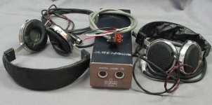
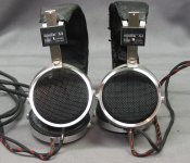
What headphone are you using btw?
Fontek electret electrostatics from the 1990's.
Attachments
Last edited:
If you have 4.7ohms internally already that’s perfect. Don’t add anymore. Thanks for sharing the details. Do you know how many volts this outputs?
I often use microwave oven transformers as inductive loads for SE Class A amps. It doubles the voltage swing. I never use the secondary HV windings - they are left unconnected. They are designed to make 2500v from 120v. I wonder if I tapped into them I could get a nice transformer coupled Class A electrostatic headphone amp! They sure are quiet.
Look at the MoFo amp as an example.
- Home
- Amplifiers
- Chip Amps
- Xmas Amp - Dibya's TDA7293 by Jhofland