Your layout is very symmetrical. but the power inlet is right next to the input of one board and the output of the other. I tried to keep the ac away from the audio part of the amp.The heat sinks seem to be crowded against the back wall too. What VA are your transformers that would have a bearing on the 20 g. switch harness.
In my build, I kept the ac as far from the boards as possible and it is very quiet. But it is your amp and please do as you see fit.
In my build, I kept the ac as far from the boards as possible and it is very quiet. But it is your amp and please do as you see fit.
SL, Vunce & X,
All good suggestions gentlemen. I have only so much real estate to play with. Also do not forget, this is a temporary home for the Xmas Amp.
SL, appreciate the fact about the AC being close to the amp boards. I was hoping that the AC mains/ emi filter combined with a short 6"-8" twisted wire running to the soft start board should be OK. Also the transformers are Antek AS2225, 200VA with 25V secondaries. Also I have vent holes drilled underneath the HS's.
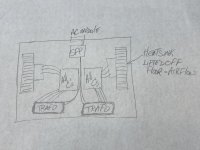
Vunce, If I put the HS's on the side of the enclosure either at the front or the back, like in your diagram, it can be done with tight spacing. See the 4 pics attached depending on changing position of transformers & HS's.
The only other way to free up space is to get rid of the side panels and bolt the HS's to the base of the enclosure (ie: HS on outside of base), but then I have no place for the rca inputs and the speaker binding posts due to no side panels.
** X, you can chime in with what you think about the possible AC interference in my original layout and whether it is something to be concerned about.
*** If I make a change: Tranformers at the back or Transformers at the front. I think Transformers at front due to rca & speaker binding posts at backs.


All good suggestions gentlemen. I have only so much real estate to play with. Also do not forget, this is a temporary home for the Xmas Amp.
SL, appreciate the fact about the AC being close to the amp boards. I was hoping that the AC mains/ emi filter combined with a short 6"-8" twisted wire running to the soft start board should be OK. Also the transformers are Antek AS2225, 200VA with 25V secondaries. Also I have vent holes drilled underneath the HS's.
Vunce, If I put the HS's on the side of the enclosure either at the front or the back, like in your diagram, it can be done with tight spacing. See the 4 pics attached depending on changing position of transformers & HS's.
The only other way to free up space is to get rid of the side panels and bolt the HS's to the base of the enclosure (ie: HS on outside of base), but then I have no place for the rca inputs and the speaker binding posts due to no side panels.
** X, you can chime in with what you think about the possible AC interference in my original layout and whether it is something to be concerned about.
*** If I make a change: Tranformers at the back or Transformers at the front. I think Transformers at front due to rca & speaker binding posts at backs.
Pictures 3/4 would be my preference. Trafo’s in the front, signal wiring towards rear. Move the speaker DC protection boards to the rear panel close to the binding post for short wire runs.
Whatever way you decide, do not put the trafo’s at the rear panel as in pics1/2.
Whatever way you decide, do not put the trafo’s at the rear panel as in pics1/2.

zek, great minds think alike. To try and gain space I have completely redesigned the layout and have the heat sinks on the outside of the enclosure. Spent the day drilling new holes and lining things up. This leaves me with only the back panel with the input jacks, speaker posts and the SSR speaker protection. Will post a pic soon. Parts came in for the FH9, so working on both.
This is the layout I would prefer to move forward with as it gives me the most space, keeps the AC in one area and the amp boards as far away as possible. Star hub (dirty) ground will be between the soft start and the transformers.
Can the purple electrostatic shield wire's from the AS2225 transformer's be coupled together and then connect to the dirty star hub ground or should they be kept separate. ?


Can the purple electrostatic shield wire's from the AS2225 transformer's be coupled together and then connect to the dirty star hub ground or should they be kept separate. ?
If these really are shield windings with just a single wire brought out, you need to connect them to PE.
Best regards!
Best regards!
Thanks KP. If I understand correctly, I will crimp connect the shield windings wire along with another wire to the PE connection on the All Cees psu, which will continue to the star chassis ground. The mains ground will also connect at the star chassis ground. Sound OK?
Regards
Regards
Do you intend to install a IEC mains inlet? In this case I'd connect the shields directly to it's PE lug in order to have protective earth with as low as possible resistance.
Best regards!
Best regards!
I have a mains/emi filter installed on the back panel (see pics in post #829). So 2 shield wires and a chassis ground wire crimped to the ground lug of the mains inlet, and then ground wire attached from mains lug to chassis or star ground. Pic below.

I didn't notice that. You don't need to solder on already crimped connections. Instead, attach both wires to the same screw that connects PE coming from your filter to the case. Use toothed washers.
Best regards!
Best regards!
Thanks Kay, so if I understand, I will ground the power entry module to the case/chassis (as usual), and then connect the 2 shield wires to that chassis connection.
Regards
Regards
All of your “ground” and trafo shield wires should connect to that single point on the chassis. Terminate your trafo shield wires each with its own ring crimp. This enables you to install/remove a trafo without it being connected to the other via a common ring crimp.
Have found some time to work on the " dirty ground" star hub for the Xmas amp build. Basically the 2 transformer shield wires, the 2 PE from the All Cees psu, the 2 glb on the amp boards, and the ground from the IEC mains module, are all connected to a ground on the chassis. Please see attached image.
I have not grounded the heat sinks "Is it necessary" ?

I have not grounded the heat sinks "Is it necessary" ?
Yes, you should ground the hestsinks. It can help to reduce noise and hum. I tied mine to the bolt that clamps the chip amp to the sink.

- Home
- Amplifiers
- Chip Amps
- Xmas Amp - Dibya's TDA7293 by Jhofland