Thank you so much.
One more question!!! How far is the baffle from the aperture on the bottom or the angle of the baffle were the driver mounts?
OB
One more question!!! How far is the baffle from the aperture on the bottom or the angle of the baffle were the driver mounts?
OB
The basic dimensions are here:
XKi - X's ab initio Karlson 6th Order Bandpass
I don’t know what the angle is, but the depth of the slanted board is 4in from the front
XKi - X's ab initio Karlson 6th Order Bandpass
I don’t know what the angle is, but the depth of the slanted board is 4in from the front
X15 used around 23 degrees . If I were trying a "new" K15 size coopler without the front shelf, then would go with ~23 degrees for a more shallow front chamber and more height. The shape of the front chamber above the baffle sets a lot of the front chamber volume. Carl appeared to use an ellipse rotated where it looked like a bass clef symbol.
Here's how Karlson stated the effects of the angle in the 1951 "Acoustic Transducers" patent. His patent reads a lot better and direct than most I've seen.
An examination of Figs. 1, 2, 3, 4 will show that all of said tapered aperture coupling chambers have been designed with a diminishing interior cross section starting near the apex of each aperture and narrowing down to a minimum at each base of said aperture. The inclined planes thus presented to the energy being propagated toward the tapered aperture end of each coupling chamber deflects said energy upward through said tapered aperture. This action assures a more uniform release of said energy over the entire length of said aperture than would be normally experienced by a uniform cross sectional area. In addition to this feature a minimum discontinuity is also presented at the open ends of said coupling chambe'rs by this structural design.
A less obvious result of the inclined plane so created in the path of the enclosed sound waves is in its influence of the radiation pattern of said coupling chamber. Properly designed relative to the rate of taper in the aperture, a uniform distribution of energy can be realized over the entire length of said aperture, especially for the high frequencies. When this occurs a roughly semi-cylindrical wave front results. This constitutes an ideal manner of propagation of these sound waves since the high frequencies will not be sharply beamed in any one direction.
If the angle that said inclined plane makes with the plane of said tapered aperture is greatly increased, several effects may be observed. Among these are (1) lower frequency limit (2) increased reverberation time (3) poorer transient response and (4) less uniformity in the radiation pattern throughout the frequency range. Obviously, optimum results for any particular application would be subject to some trial and error tests.
Pretty close to post 998 dimensions which calculate 24.22° whereas 4" and 8" calculate 26.6°.
My son dropped by with dinner and I played Dreams and Wipeout on the XKi PA130-8s and he was impressed.
Hi,
has someone already built an XKi with a TB W-1772 and there is a drawing about it.
Kind regards
has someone already built an XKi with a TB W-1772 and there is a drawing about it.
Kind regards
- don't know if one has been built yet (?). XRK971 sketched details of a rather large version
my sim for a tiny version with 21 liter back chamber

X's cabinet

my sim for a tiny version with 21 liter back chamber
X's cabinet
thank you Freddi,
if I would build the larger version.
I want to come under 50 Hz, is that possible.
if I would build the larger version.
I want to come under 50 Hz, is that possible.
Here's X's post with sims of that 1772 cabinet from six years ago. He stated 43Hz - f3
https://www.diyaudio.com/forums/ful...-initio-karlson-6th-bandpass.html#post4198019
https://www.diyaudio.com/forums/ful...-initio-karlson-6th-bandpass.html#post4198019
do you guys think the following arrangement would play pretty smooth? I imagine the narrow upper part of the aperture would act more as a lowpass filter than useful dispersive element.

@Freddi It's tough not having a project right now. I don't have need of another box but am planning to play with my scaled K8 and my K12 guitar cab this summer. Maybe some inner ducting experimentation.
I think that box could near 100dB@60Hz for 2V input w. 2x Kappa12a. For more displacement Dayton's inexpensive PA310 could be used.
here's a rough estimate of a single Kappa 12a in 44 liters

here's a rough estimate of a single Kappa 12a in 44 liters
Danke Freddi,
Die Entlüftungskante zur Vorderkante der Box beträgt 2,0 Zoll, ist das in Ordnung?
Ich habe die Dimension in der Zeichnung in Rot eingegeben.
Dirk

Die Entlüftungskante zur Vorderkante der Box beträgt 2,0 Zoll, ist das in Ordnung?
Ich habe die Dimension in der Zeichnung in Rot eingegeben.
Dirk
Hi, do you think it's a good idea to build five Xki W5-2143 for home theater? my room is quite big (20'large, 36'long, 10'high but with slanted ceiling)
thank you !
thank you !
Try making two first to see if you like it. 🙂
For the center channel I would do this as low profile and intelligibility is important.
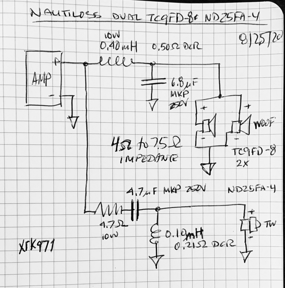
Dual TC9FD and ND25FA-4 in MTM sideways sealed box. About 4 to 5 liters volume line walls with melamine foam and stuff with fiberglass. Use this XO:
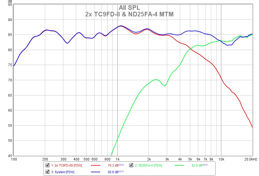
Measures well and sounds great:
The Nautaloss Ref Monitor
For the center channel I would do this as low profile and intelligibility is important.
Dual TC9FD and ND25FA-4 in MTM sideways sealed box. About 4 to 5 liters volume line walls with melamine foam and stuff with fiberglass. Use this XO:
Measures well and sounds great:
The Nautaloss Ref Monitor
- Home
- Loudspeakers
- Full Range
- XKi - X's ab initio Karlson 6th Order Bandpass