*ATH AD900 ‘Air’ are the phones I’m using. Will try with the Koss and Bose (non noise cancelling) later tonight.
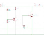
Hi bonsai first off all fantastic amplifier design it sounds fantastic(i did make myself a new pcb design as i wanted to try out the baxandall active volume control and stuff) , anywho let me get to the point everything does work, but even after adding rather substantial heatsink the transistors still reach the 120 degree point and cut off, so i wanted to ask what could be the reason for it to heat up this much (i am powering it with 18volts +- ) i shall add in the schematic of how i did it and if you could kindly check and tell if i forgot to change something to tweak it for the +- 18 volts or if i forgot to add something additional .
Regards
Regards
Attachments
Izerotwo, your bias controller is not connected properly. The 560 Ohm resistor goes from the base of the transistor to the emitter of the top output transistor.
You also have the bias controller collector and emitter swapped in your drawing. Here below are the correct connections

You also have the bias controller collector and emitter swapped in your drawing. Here below are the correct connections
Last edited:
First of all thanks for the reply and,Oh wow I really did screw up there huh, i am still surprised the amp even makes sound, i flipped the bias controllers and wrongly didnt connect a few things. Time to retrofit the board i suppose.
Another question should i remove the 560 ohm resistors right before at connecting the bd140 and bd139 to power ?Also i am a bit confused as the older model to the HPA1 had a ccs which had bd139 connected to the negative rail on that one.
regards
Another question should i remove the 560 ohm resistors right before at connecting the bd140 and bd139 to power ?Also i am a bit confused as the older model to the HPA1 had a ccs which had bd139 connected to the negative rail on that one.
regards
Sorry, I don't understand the first part of your question.
For the part about the CCS, I removed these in the most recent design because the benefits in distortion improvement are really not worth the additional complexity IMV. If you want to chase ever lower ppm numbers, then by all means use the CCS, but it will not make one difference to the sound.
🙂
For the part about the CCS, I removed these in the most recent design because the benefits in distortion improvement are really not worth the additional complexity IMV. If you want to chase ever lower ppm numbers, then by all means use the CCS, but it will not make one difference to the sound.
🙂
Ah what i meant is should i still keep this 560 ohm resistor which is connected to the ccs transistors. And I do know there wont be much of if any improvement to audio i just wanted to yolo it honestly. And actually what i meant for the second question is in the older design (the pdf that is ) you connected the bd140 to the positive rail but in the diagram you sent the opposite is true so i was just confused.
regards
regards
Attachments
Those 560 Ohm resistors you are showing are too high in value, so they will cause problems. I my original design I showed 27 Ohms which was in fact too low, so the opamp had to sink and source too much current and provide drive to the OPS. Change them to 150 or 220 ohms. This will give you 3-4mA which the opamp can sink and source easily without running into distortion problems.
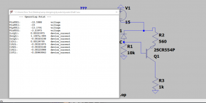
OK - you are using an LED - sorry I overlooked that. You should be good to go with 560 Ohms then. To check the actual current, just measure the voltage across the 560 Ohm resistor.
After making a modification ( a very scuffed looking one going to be honest here lol ) the amps do finally work and whilst they do heat up which is normal i found out that the left side decoupling cap whilst being measured by the multimeter seems to read out 800 uf which i found to be weird and then checking right side it was as expected near the 220uf. But even after a week of checking if anything is off i was not able to find anything wrong. So if you have any idea of what could be possibly wrong could you suggest as then i could maybe then check more better. Also yeah it was an LED i felt LEDs would look cool and as they are rather fast they also would work well here. Again thanks for all the previous help.
Regards
Regards
Oh yeah i also had to mention, there is audible distortion on that side only when i raise the volume. Yeah i could try to do that will report soon,
Regards
Regards
Something is not right. With the input shorted, can you also measure the voltage at the output.
Not sure how i am supposed to short the input as i have the volume and balanced to single ended conversion.
oh i found out more weird things that side after turning it off has an extended noise . Also measured the voltage drop on the left side and it was .1 volts whilst on the right side it was 0
Oh wow a plot twist now that i tested the amp the side with the 800uf cap is the correct one time to see what that side has wrong with it. .
Regards
Regards
ok i have finally found the issue the side where it only read 220 uf, the 1 ohm resistor for it wasnt properly soldered and hence, wasnt making connection and fixing that has fixed all the mentioned issues.
Regards
Regards
Make sure that with no input (short the 1st opamp non inverting input to 0V) the output measured no more than +- 3.5 mV.
Good that you have made progress.
Good that you have made progress.
It’s a very important check - you don’t want DC on the output because it will affect the sound if it is large - it’s a basic check that lets you know the output stage is working ok.
- Home
- Amplifiers
- Headphone Systems
- X-Altra HPA-1 Class A Headphone Amplifier