
Hello, The link to the BOM for the HPA-1 is fixed
https://hifisonix.com/projects/hpa-1-class-a-headphone-amplifier/
https://hifisonix.com/projects/hpa-1-class-a-headphone-amplifier/
So i tried many of the steps you suggested, but as one of the transistors was heating up like there was no tomorrow i couldn't really keep it on for long.
Things i already tried
Remove the Large Filter Caps
Change out the LEDs to ultra low power ones
remove the tweaks i made to Gain and changed it back to the default 3x
After all of this i also checked my design but couldn't really find any issues.
Other than the lack of c7/c14 from the original design which was missing (could this be the root cause of all the problems ? as its missing on both sides)
I also noticed that even when i removed the LED from the CCS (the equivalent to the 4.7k resistor r10/r27) the Transistor in question still heated up to be the next sun. and also noticed that the resistance between its Legs was near 2k compared to roughly 15k on the other channels transistor
Is there a possibility the transistor is just defective? I didn't test it with my tester prior to soldering it.
Kind Regards
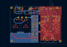
Attachments
If anyone is interested I have an X-Altra HPA for sale, fully built and working perfectly. Fitted with OPA1656, Toshiba transistors, Susumu and Vishay MELF resistors.
Excellent little head amp. I have a second PCB that I will try some different Sanken transistors and option to roll op-amps.
Will include a good PSU board with sale. Will also place this in the swap meet.

Excellent little head amp. I have a second PCB that I will try some different Sanken transistors and option to roll op-amps.
Will include a good PSU board with sale. Will also place this in the swap meet.
I don’t see the inductors, did you try it with the output zobels? According to Andrew they were added to improve the voicing. I need to pull mine out and give it a try as it was after I built mine he made the change. Your smd works looks good, not sure why some are dragging their feet it actually is easier to build in my view.
Bill
Bill
Sorry for my tardy reply. I’ve been travelling for a few weeks. Please can you repost the schematic - the one from your earlier post is pretty corrupted and almost impossible to read.So i tried many of the steps you suggested, but as one of the transistors was heating up like there was no tomorrow i couldn't really keep it on for long.
Things i already tried
Remove the Large Filter Caps
Change out the LEDs to ultra low power ones
remove the tweaks i made to Gain and changed it back to the default 3x
After all of this i also checked my design but couldn't really find any issues.
Other than the lack of c7/c14 from the original design which was missing (could this be the root cause of all the problems ? as its missing on both sides)
I also noticed that even when i removed the LED from the CCS (the equivalent to the 4.7k resistor r10/r27) the Transistor in question still heated up to be the next sun. and also noticed that the resistance between its Legs was near 2k compared to roughly 15k on the other channels transistor
Is there a possibility the transistor is just defective? I didn't test it with my tester prior to soldering it.
Kind Regards
The design originally used a 3.3 ohm resistor to couple the amp output to the headphones. An inductor in parallel with the resistor was added later. Let’s get your headphone amp going with the 3.3 ohm then fit the inductor.
(Never use transistors or any semiconductors from eBay vendors. If they are not from a reputable supplier, you are very likely to run into problems).
Last edited:
I don’t see the inductors, did you try it with the output zobels? According to Andrew they were added to improve the voicing. I need to pull mine out and give it a try as it was after I built mine he made the change. Your smd works looks good, not sure why some are dragging their feet it actually is easier to build in my view.
Bill
No Bill, no inductors and no zobel network, did you fix this direct to the RCAs? I missed this in the thread. I will try this with the next build soon.
I had a small protection module in mine.
Can you show me a pic of yours (I mean the HPA, no anatomy please 😉 )
@Bonsai - Andy will you be including inductors and zobel in any new versions, also maybe provide footprint for DIP adapters to roll?
Hey thanks for the reply, I actually forgot to update but i was luckily able to figure out why the transistor was heating up luckily the transistor wasn't defective and it wasn't working for the stupidest reason yet.Sorry for my tardy reply. I’ve been travelling for a few weeks. Please can you repost the schematic - the one from your earlier post is pretty corrupted and almost impossible to read.
The design originally used a 3.3 ohm resistor to couple the amp output to the headphones. An inductor in parallel with the resistor was added later. Let’s get your headphone amp going with the 3.3 ohm then fit the inductor.
(Never use transistors or any semiconductors from eBay vendors. If they are not from a reputable supplier, you are very likely to run into problems).
There was a small solder bridge between emitter and the base of the PNP transistor (shame that i only found this after i blew up my test earphone and noticed almost a 10v DC on the right side),and now luckily its no longer heating up though it still isnt making sound (currently waiting on a new linear pot as my trusty old one gave out(which i am hoping is why the system didnt work).
Yes i am basing it of your older design prior to the addition of the inductor, actually the second build i am basing off your design and back then i did remove the 3.3 instead using a dead short, and i just used that same schematic as a starting point.
And yes i did purchase the transistor from mouser,as i too have often had issues from random amazon/ other ecom sellers.
Again thank you for your reply! And hoping you had a good travel!
Regards
Attachments
Hi, please don’t use the HPA1 circuit without the 3.3 ohm resistor or the 3.3 ohm in parallel with a coil. These components are needed to isolate any cable capacitance from the amplifier (this is the same technique used in power amps BTW).
I did consider using a DIP but then you are very limited to the range of opamps. If I do another spin of boards, I will look at placing a DIP in parallel with the SMD footprint for builders that want that option. Ditto a bigger area for the output L.
Thanks for the feedback.
I did consider using a DIP but then you are very limited to the range of opamps. If I do another spin of boards, I will look at placing a DIP in parallel with the SMD footprint for builders that want that option. Ditto a bigger area for the output L.
Thanks for the feedback.
Seems like you added an extra buffer stage between the opamp and the output devices. I would have to look at how this might affect the loop stability to know if this is an issue or not.Hey thanks for the reply, I actually forgot to update but i was luckily able to figure out why the transistor was heating up luckily the transistor wasn't defective and it wasn't working for the stupidest reason yet.
There was a small solder bridge between emitter and the base of the PNP transistor (shame that i only found this after i blew up my test earphone and noticed almost a 10v DC on the right side),and now luckily its no longer heating up though it still isnt making sound (currently waiting on a new linear pot as my trusty old one gave out(which i am hoping is why the system didnt work).
Yes i am basing it of your older design prior to the addition of the inductor, actually the second build i am basing off your design and back then i did remove the 3.3 instead using a dead short, and i just used that same schematic as a starting point.
And yes i did purchase the transistor from mouser,as i too have often had issues from random amazon/ other ecom sellers.
Again thank you for your reply! And hoping you had a good travel!
Regards
Can you remove the BD139/140 devices?
I actually was using the bd 139/140 as a replacement for the 4.7k resistors (to act as a better ccs), this was based on your original x altra design and actually did work fine on my older amp with the same design. But yes I will try removing the bd1xx pairs and replace them with a resistor if all else fails.
Leave them in for now. Can you short the input and then tell me what the output voltage is? Measure the voltage at the non inverting input of the second opamp ie the opamp driving the output stage.
Passive,
I had mine originally in a case with the power supply/ transformer in the back and hp amp in the front. I had a problem with the input picking up hum from the transformer. I rebuilt it into Andrew’s preamp and the wiring routing was much better and quieter. This was before Andrew added the inductors. I was listening with Sennheiser 800s. Now I listen mostly with planer magnetic headphones through a Schiit MJ3 fed strait from the DAC. I need to revisit a few things inside the preamp and add the inductors to the hp amp portion.
Bill
- Home
- Amplifiers
- Headphone Systems
- X-Altra HPA-1 Class A Headphone Amplifier