BTW if anyone has the frd/zma files for the H1499 27TBCD/GB-DXT tweeter I would appreciate it. Thanks.
Hi, Im looking to build a 2 way speaker similar to the Harbeth 30.2.
Jim, I honestly think you can improve that rater "old fashioned" Harbeth design.
The 8" driver beams somewhere between 1-2 khz giving directivity issues. I experienced this on my quite similar Spendor speaker, which makes it sensitive to positioning in the room.
Consider lowering the crossover to 1.5 khz for a much smoother transition, the 1.5" Seas Excel T35 tweeter can do this. Use a DSP for an active, flexible and easy setup. I find the MiniDSP 2x4HD suitable, it can also work as a convolver for linear phase filters and time-align drivers. The downside is that you need an extra stereo amp. Good luck with the project.
Last edited:
Cheers to System7 for the no nonsense posts...
As to the TS, get proper measurements before you make decisions. And/or go practice on 8"-1" combo's in Boxsim because of the quite extensive and reliable database (not want to pass VituixCAD, but that lacks the data). Imho you will get better results with -say- a GF200 and a G25 FFL with and without WG148 simmed than some other combo without proper development.
As to the TS, get proper measurements before you make decisions. And/or go practice on 8"-1" combo's in Boxsim because of the quite extensive and reliable database (not want to pass VituixCAD, but that lacks the data). Imho you will get better results with -say- a GF200 and a G25 FFL with and without WG148 simmed than some other combo without proper development.
Jim, I honestly think you can improve that rater "old fashioned" Harbeth design.
The 8" driver beams somewhere between 1-2 khz giving directivity issues. I experienced this on my quite similar Spendor speaker, which makes it sensitive to positioning in the room.
Consider lowering the crossover to 1.5 khz for a much smoother transition, the 1.5" Seas Excel T35 tweeter can do this. Use a DSP for an active, flexible and easy setup. I find the MiniDSP 2x4HD suitable, it can also work as a convolver for linear phase filters and time-align drivers. The downside is that you need an extra stereo amp. Good luck with the project.
yea after some thought I think I like it because it is not as strident as my DIY speaker it has a very mellow midrange, maybe a little too much so. So I am regrouping and trying to come up with some strategy. While I am doing that I am running some SIMS. I like the idea of the SEAS A26 driver as I just happen to have a cabinet it will fit into even the driver cutouts and recess. I was thinking 2 way with the SEAS tweeter but I believe there is a post that advises against a 10 inch 2 way so I can make it a 3 driver design. I know it will be more complicated.
Cheers to System7 for the no nonsense posts...
As to the TS, get proper measurements before you make decisions. And/or go practice on 8"-1" combo's in Boxsim because of the quite extensive and reliable database (not want to pass VituixCAD, but that lacks the data). Imho you will get better results with -say- a GF200 and a G25 FFL with and without WG148 simmed than some other combo without proper development.
I just looked up the GF200 and G25 FFL. I have lots of time to play and Sim. I use XSIM (is that OK?) Thank you for your suggestions
yea after some thought I think I like it because it is not as strident as my DIY speaker it has a very mellow midrange, maybe a little too much so. So I am regrouping and trying to come up with some strategy. While I am doing that I am running some SIMS. I like the idea of the SEAS A26 driver as I just happen to have a cabinet it will fit into even the driver cutouts and recess. I was thinking 2 way with the SEAS tweeter but I believe there is a post that advises against a 10 inch 2 way so I can make it a 3 driver design. I know it will be more complicated.
There are plenty of posts advising against that and many other things, but that doesn't necessarily make them true, or universally applicable. 😉 A 3-way is arguably preferable, but it depends on your priorities. The Seas A26, which is a direct descendent of the Dynaco A25 is simple & liked by many, albeit not the most refined under the sun. You may wish to look up the World Designs WD25 variations; Peter Comeau was largely responsible for getting Seas to make the driver in question in the first place, and he created a somewhat more refined design with three different tweeters tracking, as I recall, a quasi-LR3 topology, which gave better control over the midbass driver's rolloff & decent protection to the HF unit. It wasn't bad at all so probably worth a few minutes to take a gander.
I do know how it works, guys. Just try not to bore and confuse 95% of people who don't have a technical background.
Which is a bit like saying 'it's better to write something incorrect because I think it's easier'. If you make misleading or inaccurate statements you should expect to get called on it sooner or later.
F.I.R. filters were practically invented by my old digital and analog Tutor
When was this?
How he enjoyed telling us that his arch-rival Professor "Whatshisname" of Gottingen University had published a design for some F.I.R. digital filter to World acclaim. He went on to explain that he had found, to his delight, a glaring Mathematical error in the circuit. 😀
Always some rivalry, right?
The circuit was UNSTABLE under feedback. Invited us to evaluate the z-transform. Which he had also invented. 😕
Some still think it is and I have also heard mixed results. But like everything else - it can work great when done right. But I absolutely agree on the simple filters - when possible.
How we laughed. Doctor Tony was a sound man before 11 AM. After that sober effort he retired to his favourite bottle of Greek Wine. To which he invited his favourite students to share.
"Sound man" Is that a pun? 😀
You can't hold down a good man. Now Professor Emeritus. 😎
I must admit to some artistic license in my FIR story, which I think is a jolly good one regardless. 😀

The astute reader like genius filter man Doctor Tony Constantinides would be well aware that it is, in fact, IIR digital filters that employ feedback. But would nevertheless enjoy the story of his technical greatness when confronted by more journeyman and humourless opposition.
That is what I learned from him. A good professional always makes it look easy. 😎
I have PM'd jimbones with my thoughts on his two pending projects rather than squabble here. A good outcome is assured.
You mean 'get called on inaccurate technical remarks', and then when attempting to deflect from them doesn't work (despite repeatedly implying your fellow forum members are idiots and only you have any knowledge) withdraw, claiming such things are 'boring'. Okey-dokey. 😉
Come on, Steve. Many of us here have a lot of respect for you. I certainly do. But do yourself a favour and give the self-aggrandising a break. You are not the only person here with a modicum of knowledge, and repeatedly implying that you are, and that most other people here are fools, is downright rude, especially when you haven't got your own facts right. You help a lot of people, and I'm sure most (not just those you directly assist) appreciate that very much indeed -I'd actually like to take the opportunity of thanking you for doing so; you're a major asset to the forum for that, and for the entertainment. But it's not a free pass to repeatedly insult other people's intelligence, or to make misleading statements. It's not necessary -and everybody knows you're better than that, me old mucker.
Be that as it may, I trust the projects in question will indeed work out well.
Last edited:
If and only if you know how to import the data. To my knowledge, Xsim doesn't correct for the outer shape of the enclosure ('Baffle step' amongst others), so a manual correction would be obliged. I'd take my chances and move over to either VituixCAD or Boxsim (the latter being simple, quite intuitive and quite spot on too).I just looked up the GF200 and G25 FFL. I have lots of time to play and Sim. I use XSIM (is that OK?) Thank you for your suggestions
Furthermore some of the statements are an outright insult to those on DIYA who actually measure (some here measure up to 18 angles as per Kimmosto) before starting to sim a design. Claiming the slope is BUT 3 where it actually is BUT 6 is no minor slip in my book.
Mr. Boden, you are like a Dog that won't let go of a bone, if I have the metaphor right. 🙂

I would say my third order filter is a bit butterworthy in certain respects. The one you roadtested was another of my creations a 4th. order phase-aligned Linkwitz-Riley circuit.
This is as Butterworthy as I can get it under the circumstances:
Hope that clears it up.
I would say my third order filter is a bit butterworthy in certain respects. The one you roadtested was another of my creations a 4th. order phase-aligned Linkwitz-Riley circuit.
This is as Butterworthy as I can get it under the circumstances:
Hope that clears it up.
The one you roadtested was another of my creations a 4th. order phase-aligned Linkwitz-Riley circuit.
Actually, as has been noted, closer to LR6 since neither driver even remotely follows 4th order acoustic transfer functions, according to your own data. This has been noted above, but you're still repeating the same misleading statement.

Purely for what it's worth, having had a few minutes spare after walking the hound, I dug through my archive of measurements, and thought I'd see what I could quickly simulate.
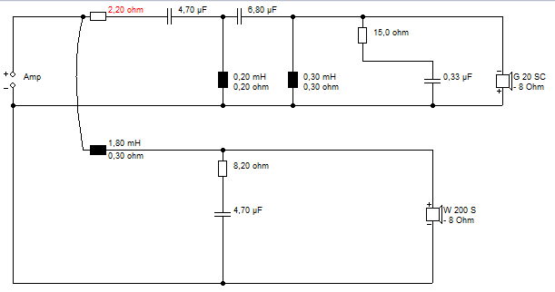
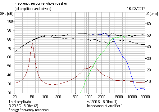
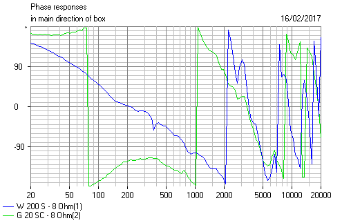
Like all such simulated 'designs', a la Steve's above (or anybody else's for that matter) it's not a 'design' as such at all: the baseline measurements are mine, but reprocessed to add projected box load (60 litre, Fb 30Hz) baffle-step and diffraction effects (28in x 11.5in baffle, 3/4in roundover, 13in between driver vertical centres, 1.2in z-axis offset). The drivers are the Scan Speak 22W/8534G00 and the SB Satori TW29RN-B, HBT minimum phase extracted. So (and I want to stress this point) this is very rough & ready, and I don't pretend it is anything beyond that: it is certainly not a finalised design, just an approximate exercise. I used the ring-radiator as a nod to Steve, since I know he's a fan.
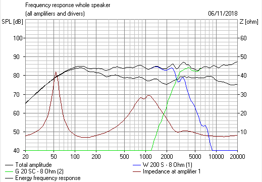
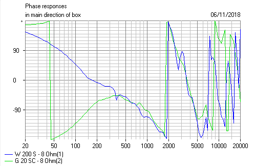
01 shows the raw driver response. 02 is the summed FR with filters in place, 03 the same with phase. 04 summed with reversed tweeter polarity, for whatever that's worth (not a lot); 05 summed FR with predicted power-response; 06 the electrical transfer functions, 07 the system impedance & electrical phase.
Nominal crossover point is 1.4KHz, [asymmetric] LR4. The acoustic transfer functions are strictly speaking roughly 2nd order Butterworth on the low-pass & 4th order Bessel on the high pass, but the general characteristics are roughly akin to LR4 behaviour. It's a relatively low filter but the Satori can handle it OK. HD2 is a bit high, but there's no audible strain -I've crossed that thing at 1.1KHz to a quad of 6 1/2in midbass units without it protesting. Damped 2nd order electrical on the midbass, 3rd order electrical with a nominal fixed L-pad on the HF to get the phase into line. There's enough in the resistive shunt to damp the Fs impedance without needing a full LCR, although that would still be a 'safe' addition. A slightly rising response on-axis, due to the Satori being a little larger than some, so off-axis it drops a bit in the HF, as is roughly indicated in the power-response. Impedance minimum is about 3.5ohms, roughly flat-lining above ~8KHz, so not a particularly tricky load for a half-decent amplifier. Electrical phase gets to about 60 degrees around 1.2KHz, which is a bit steeper than I'd normally like, but impedance is about 10ohms at that point, so it shouldn't be troublesome.
All purely conjectural / approximate, nothing more, but an interesting exercise for an 8in 2-way. Bit different to a Harbeth, where the crossover is usually at least a KHz higher, but the general principle can work fine so long as you pick your drivers carefully.
Attachments
-
 01 raw drivers.gif24 KB · Views: 127
 -
 02 summed FR.gif22.1 KB · Views: 121
 -
 03 summed FR+phase.gif35.6 KB · Views: 108
 -
 04 reversed polarity.gif23.4 KB · Views: 106
 -
 05 summed FR+power resp.gif23.5 KB · Views: 107
 -
 06 electrical transfer functions.gif19.7 KB · Views: 111
 -
 07 impedance.gif20.4 KB · Views: 145
 -
 Simulated 8in 2-way.PNG14.9 KB · Views: 465
Last edited:
As you say purely conjecture.
I guess if you had posted cabinet details and crossover values you would not be able to buy the drivers or components for some months, due to them being sold out.
It could have generated hours of fun Xover tweaking and level matching. 🙂
Useful info that you can take the Satori tweeter that low and only 2nd harmonic distortion being a small concern.
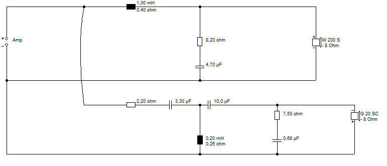
Unfortunately, this is not a design remotely useful to anyone:
No Values! Why the secretiveness? 😕
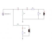
Now I can do something with this DXT design:
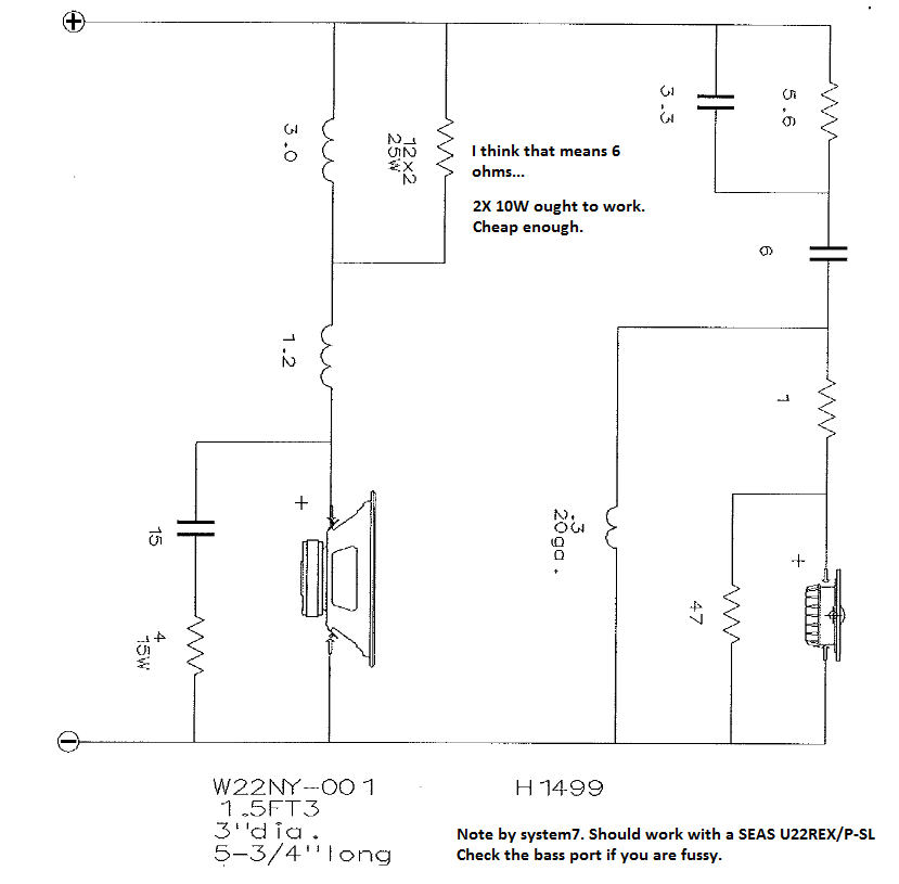
I have already hatched a potentially better scheme. Or plan on which to proceed. Because a certain amount of ducks have to be got into a row, based on exact woofer choice.
No Values! Why the secretiveness? 😕
Now I can do something with this DXT design:
I have already hatched a potentially better scheme. Or plan on which to proceed. Because a certain amount of ducks have to be got into a row, based on exact woofer choice.
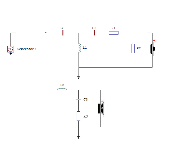
I think it might be an asymmetric design.
With 2nd order on the bass, and 3rd order on the tweeter.
Or, is it third order on the bass and 4th order on the tweeter.
I'll get my coat.
Sorry I couldnt resist, I have a day of work and have avoided going to the pub.
With 2nd order on the bass, and 3rd order on the tweeter.
Or, is it third order on the bass and 4th order on the tweeter.
I'll get my coat.
Sorry I couldnt resist, I have a day of work and have avoided going to the pub.
Unfortunately, this is not a design remotely useful to anyone:
No Values! Why the secretiveness? 😕
Simple. I clearly stated:
Like all such simulated 'designs', a la Steve's above (or anybody else's for that matter) it's not a 'design' as such at all: the baseline measurements are mine, but reprocessed to add projected box load (60 litre, Fb 30Hz) baffle-step and diffraction effects (28in x 11.5in baffle, 3/4in roundover, 13in between driver vertical centres, 1.2in z-axis offset). The drivers are the Scan Speak 22W/8534G00 and the SB Satori TW29RN-B, HBT minimum phase extracted. So (and I want to stress this point) this is very rough & ready, and I don't pretend it is anything beyond that: it is certainly not a finalised design, just an approximate exercise.
And:
All purely conjectural / approximate, nothing more, but an interesting exercise for an 8in 2-way.
Since all such 'designs' are as I stated more or less just exercises, not fully conceived, properly measured and developed loudspeakers, I didn't post the component values or full box design details since I'm not in the business of providing purely simulated offerings as recommendations. You'll recall that in practice the driver responses are likely to differ a little from this. Baffle-step loss and diffraction effects were simply simulated and spliced in (which is only ever approximate. Near, but still approximate), and their relative positions & the baffle dimensions were not carefully optimised since this was a very quick look, no more. No off-axis measurements were used either, and on-axis alone is not good enough in my book these days for a high quality loudspeaker, although I did make a small nod in this direction by adjusting the nominal summed balance to roughly what I know works well with this tweeter given its off-axis. Now, I can certainly post the values if you wish -but there isn't much point in doing so from my perspective, because they will require changing. As I made it clear from the outset this is not a 'real' design, and I have zero interest in randomly tweaking what was a pure 30 minute investigative exercise. I know some do -and power to them. That's not how I design things though.
I have already hatched a potentially better scheme. Or plan on which to proceed. Because a certain amount of ducks have to be got into a row, based on exact woofer choice.
My congratulations. Since I'm not in a competition (obviously others can speak for themselves 😉 ) the object of this exercise from my perspective was purely interest, and illustrating one of the many approaches. Which I do not claim to be definitive, 'better' or 'worse' than anything else, above all since it's not even a properly worked up design, just a quick check. That being said, 'potentially better' will rather depend on perspective and priorities.
I think it might be an asymmetric design.
With 2nd order on the bass, and 3rd order on the tweeter.
Or, is it third order on the bass and 4th order on the tweeter.
I'll get my coat.
Sorry I couldnt resist, I have a day of work and have avoided going to the pub.
As in mine? As noted, it's just a rough investigation to show one general direction rather than a proper design, so in practice it will require changing based on proper measurements & refining the baffle dimensions / driver position (which I didn't as I was only taking a quick look). However, the electrical topology is a damped 2nd order low pass, and a 3rd order high pass on the tweeter with a fixed L-pad. The acoustic slopes are 2nd order Butterworth (more or less) on the bass unit, and 4th order Bessel (ditto) on the HF, giving roughly an LR4 characteristic in terms of its general behaviour.
- Home
- Loudspeakers
- Multi-Way
- Woofer suggestion for Harbeth like 2 way