Last edited:
Your output Stage blocking capacitors should be blocking or starting to block below 10hz.
My main amp cuts below 18hz.
My main amp cuts below 18hz.
Last edited:
It looks like you have a tame HF stability and spectrum level response. Open loop response has no consequences, given your closed loop responses are ok.
You could extend your LF testing down to 1Hz, as your signal generator can manage that. You may have to use X-Y scope plot, with persistence, to get a good view of what is happening. One aim would be to step down from 10Hz in say 1Hz increments, and check if there is any significant peaking occurring down where the output transformer is rolling off. Perhaps start at low enough signal level that any peaking doesn't cause high power levels - and then step up signal a bit to see how any peaking is affected. You may find no significant changes worth reporting until well below 5Hz.
You could extend your LF testing down to 1Hz, as your signal generator can manage that. You may have to use X-Y scope plot, with persistence, to get a good view of what is happening. One aim would be to step down from 10Hz in say 1Hz increments, and check if there is any significant peaking occurring down where the output transformer is rolling off. Perhaps start at low enough signal level that any peaking doesn't cause high power levels - and then step up signal a bit to see how any peaking is affected. You may find no significant changes worth reporting until well below 5Hz.
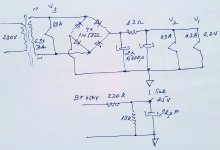
One more question please...This is my 6.3V heaters supply scheme. V1,V2 are DC suplied, V3 AC suplied. The Heaters are referenced to ground by dc return rail only. Works nice and quiet. Now, I want to elevate heaters more to say 30Vdc. from a B+ voltage divider. I wonder how is the best to reference the heater supply to the 25V elevation point please ? Should I just stack it on the top or from a virtual center tap built on ac or dc side please? Thanks.

Last edited:
Yes you could link the heater supply '0V' to the +25V node, however you haven't identified what V1, V2, and V3 are with respect to earlier schematics you've posted.
Hey. V3 is 6n6p driver stage and V2 is first stage in earlier schematic V1 is a integrated preamp stage I didn't figured. The DC supply was necessary to heat v1,v2 - 6n9s tubes. Really noisy tubes works only dc in my circuit. With AC supply - DC elevation helps with negative voltage only, positive voltage elevation did not help at all. Still, elevating by negative voltage the noise not completely gone, more the cathode resistors are not decoupled at all- who make h-k coupling more sensitive. So, DC supply rules. But with V2 6n9s into first stage /cathodyne position the inverter cathode is up 100v, and will raise it up to 125v perhaps, as consequence to get a little bit more headroom of first stage (1.5V around). A slight elevation (30V) to put Vh-k potential into the safe range I considered please. Thanks.
Last edited:
One more question please:
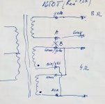
Do I have any benefit using a different secondary winding for nfb ? and not necessary the winding I used for speaker please ?
I used a Hammond 1650T. The output wiring is presented in my sketch. Decided to use the 4 ohm output only now I have a winding available. The points 'A' and 'B' was initial internaly connected but I did it apart. So, now I may use yellow / gray wires as separate winding for nfb (with the gray tied to the common). Do I get any advantage using it instead to use the 4 ohm speaker output please ? Thank you.

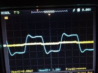
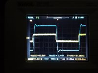
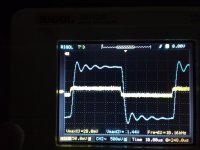
It depends on the output transformer. Some taps will offer better overall stability than others. In this case, based on your photo, I would not change a thing. That's about as good a square wave as you could ask for.
Last edited:
There is a slight difference to drive it for 4 ohm and 8 ohm impedance to onset clipping with 20db nfb applied. In 8 ohm it ask for 800 mVpk input, with 4 ohm 900mVpk for 32Vpk output. That was close for 1V initial cathode bias. It was necessary to lift it to 1.5V to get a bit of convenient headroom but this raised the grid voltage to next stage to 125V around. The 6sl7 cathodyne is still well usable biased at 2.4V around with 410V but h-k potential is way above the limit so I elevated the heaters a bit. See #105. Thanks.
Last edited:
Hey again. Quick question please: May an undampened low freq oscillation of an LC filter in power stage to create premises of low freq instability when nfb apply please ? I just thinking...my power plates are supplied from first node decoupled with 500uF cap. Next I used a 4H choke to next 500uF decoupled supply node to the screens. Still the 30 ohm residual resistance of the coil is not enough to dampen the LC network oscillation at 3.5Hz. I may use a hundred ohm series resistor to be sure I don't get any lf overshot but : Do it have any influence to improve low freq stability margin please ? (Remember my tubes are pentode connected).Thanks.
Last edited:
I'd suggest posting the power transformer details to allow a PSUD2 sim, so need PT pri and sec resistances and sec voltage and an up to date schematic. How did you measure the 4H inductance, and was that with the idle dc current ? And state the idle dc current you presently have.
The inductance measured with the lcr meter setted at 100 Hz. The idling current through 50mA. I.ll measure PT windings resistances bit later please. Thanks.
50mA per tube, so 6x 50 =300mA through the 4H choke ?
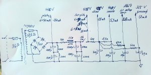
Can you link to a schematic of the power transformer and rectifier, as this is a long thread and each time you ask a query it is best to provide all the technical details relevant to the query, or at least provide notes on which posts have that relevant data.
Can you link to a schematic of the power transformer and rectifier, as this is a long thread and each time you ask a query it is best to provide all the technical details relevant to the query, or at least provide notes on which posts have that relevant data.
Last edited:
Are the 3.6 and 17.2 ohm parts the DCR's for the windings? What is the mains Vac? Is the choke now 1.5H with a 25 ohm DCR, and the 100 ohm part is a separate resistor?
PSUD2 indicates a B+ of 435Vdc for 290mA loading before the choke, and 40mA after the choke. For that scenario, the initial concern is that the secondary winding has 685mArms current, which doesn't align with your post #117 comment about the winding having a 450mA rating. Where did you identify the 450mA rating - perhaps it was a dc load rating on the secondary winding (after rectification and filtering) ?
PSUD2 can indicate circuit response for a single step load change from the output stage. I used a 290mA to 100mA step change to look for oscillatory response. That is an unreal stage load change situation (as the Williamson is class A with effectively no change to power supply loading), but does provide an awareness of likely damped ringing frequency. There is no indication of any resonance of the choke current for 125 ohm DCR, but there is a damped ring of about 10Hz for a 25 ohm DCR, which is somewhat removed from 3.5Hz. A 4H choke with 25 ohm DCR has a 5 Hz damped response to a step load current change.
That may cause an interaction if you have 3.5Hz instability due to poor margin from the output transformer and feedback, but I'd suggest is not the cause of the 3.5Hz instability, and is up to you to improve/avoid by circuit design.
- Home
- Amplifiers
- Tubes / Valves
- Williamson first stage question
