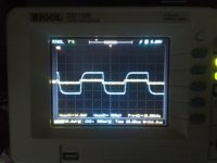
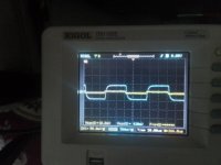
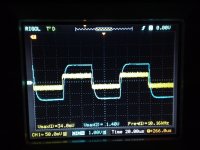
Perhaps time to do a frequency response test with resistor load. If you have no software tool, then spot frequencies are fine to clarify where the peaks and dips may be as you change frequency - hopefully it is flat from the lowest to highest frequency sinewave you can generate. The response may change as you increase the output voltage (power), especially at low frequency end. It doesn't seem like the amp will become unstable, although its best to keep an eye on say B+ level in case it dips, and the scope should also indicate if something goes awry.
Thanks. No software tools. I used an analog 1Hz-1MHz low frequency generator 600ohm output. It claims 0.02 distortions but my probes/test leads are crap.
Nice work! If your signal generator has a sweep function, you can set it to a slow speed and watch the sine waves for any excessive rise or fall. If you spot something, narrow it down. That amp is probably going to start rolling off after 20kHz, which is okay.
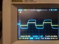
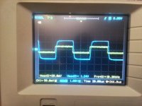
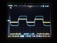
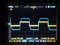
Ok. I did some measurements starting with 10 Hz to 40kHz from octave to octave with 100mVpk at the input as follow:
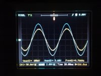
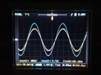
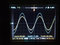
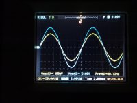
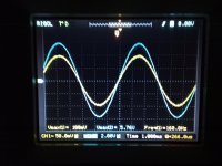
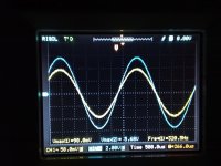
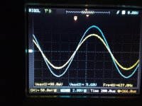
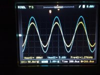
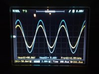
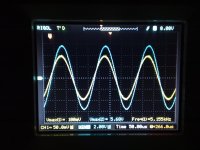
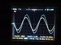
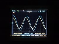
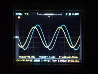
It seems pretty consistent from 10Hz to say 15KHz. The signal start to roll off below 20kHz . I think is more a matter of 22k grid stopper I used on the first stage. What do you think please ? Thanks.


It seems pretty consistent from 10Hz to say 15KHz. The signal start to roll off below 20kHz . I think is more a matter of 22k grid stopper I used on the first stage. What do you think please ? Thanks.
Last edited:
I don't think you need the second 22K grid stopper, but I'll let Tim chime in. Definitely getting some rolloff at 20kHz, also some phase shift, If I'm reading that correctly.
Yes indeed, but only minimal -0.5 db at 20kHz. To not forget the OT is not a state of art but ordinary of the shelf Hammond 1650T ( very decent for ordinary applications btw.)
Last edited:
...I don't think aso. That's my bad habit to start installing something into grids as a preemptive measure to get not trouble as building progress. It was happen to remain in circuit and I figured in my drawings aso, but don't think is a matter to worry about....You may understand I.m a truck driver learned to build amps from tutorials...🤣🤣I don't think you need the second 22K grid stopper, but I'll let Tim chime in.
Looks to me like no gremlins are lurking. Is that with your latest "250pF only over plate with 250pF over feedback resistor"?
You should be able to use the amp as is, so enjoy. For your own interest, you could do more testing, although you may be at your natural limit of convenience without additional tools anyway.
Wrt your amp, if you disconnected the feedback and repeated the frequency response manual sweep, you would likely notice the open-loop gain would start falling above about 1kHz, as you are slugging the HF gain with that '250pF over plate' which is making the amp quite stable at HF when feedback is applied. That means closed loop distortion above 1kHz is likely increasing, but that may only show up with software/soundcard or a vintage distortion meter. That may also be the reason for your noticeable phase shift and gain droop above 10-20kHz, as feedback starts to lose its effect, more so than the OPT or grid-stopper influences.
Hey. No. The last HF compensation scheme did not include nothing over the first plate resistor (see #70). Only a 220pF ( 230pF measured) over 15k series feedback resistor was used. I think a little bit less value ( like 200pF or so) it worth to try to improve the front at 10khz. But as have nothing like 180-200pF in hand to try I will never know. The actual circuit with the last measurements presented is exactly the one from #75 please. - Only 220pF over nfb resistor and a 22k grid stopper into first grid. No snubbers over first plate.
Last edited:
You can 'make' a lower value capacitor by using two capacitors in series - eg. 220pF+220pF in series will become a 110pF cap.
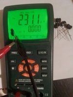
Clear thing, but with such low value the ringing is still present. Already tried. The "best" compensation should be 200pF around but have not in hand small values variation to exactly tailor with. 220pF I used, and maybe bit more (250pF, 500pF) will improve HF stability perhaps, but with a price. 230pF is exactly measured I used.
Last edited:
It seems I cannot improve the rising time in actual configuration and initial 230pF work the best...😕 May be the OT limit please ?
- Home
- Amplifiers
- Tubes / Valves
- Williamson first stage question
