I thought about using those

Through center of the coil and holes in pcb...... what about third one? It will be on separate board but it won't be more than 15-20 centimetres away
Through center of the coil and holes in pcb...... what about third one? It will be on separate board but it won't be more than 15-20 centimetres away
If you want to save money buy a second hand sony QS or ES amplivier, or a heavy pioneer.Do you have any idea on amp I could build to match those?
when you want te build simple and high qaulity use two 180W class D modules of hypex.
Advantage constant low distortion, load independent behaviour.
No cross over distorsion.
They cost 72euro inclusive tax a pice. Other options are more exspensive i gues.
https://www.hypexshop.com/.
Then you need a 300-400VA transformer, capacitors diode bridge to make +45V -45V.
And a metal housing as cooling is it enough to fix the modules to the metal case.
It is a powerfull amp works fine if the speaker Z>1 ohm Iout<10A
datasheet http://www.hypex.nl/docs/UcD180HG_datasheet.pdf
You do not need a pre-amplifier a quality potentiometer (alps 50- 100K log) is enough.

You can build the selection switch and potentiometer in a other case and make a passive pre-amplifier.
Attachments
Last edited:
Maybe is the Lm3886T a nice solution to save money.
I think you can use the power supply of the unitra to power these modules with can have a 4ohm load 68W and 38W in to 8 ohm.
LM3886T datasheet, Pinout ,application circuits High-Performance 68W Audio Power Amplifier With Mute
2PCS,LM3886 LM3886T Audio Power Amplifier w/Mute IC NEW - eBay, ICs Processors, Electronic Components, Electrical Test Equipment, Business Industrial. (Eindtijd 12-sep-10 13:14:39 CEST)
In Your Neighborhood
DIY Granite Speakers with Seas G17REX/P and 27 TFFC Drivers
DIY Granite Speakers with Seas G17REX/P and 27 TFFC Drivers
Of course, you may subtitute wood for the granite.
Regards,
WHG
DIY Granite Speakers with Seas G17REX/P and 27 TFFC Drivers
DIY Granite Speakers with Seas G17REX/P and 27 TFFC Drivers
Of course, you may subtitute wood for the granite.
Regards,
WHG
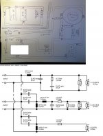
What do you think about the coil placement?
An externally hosted image should be here but it was not working when we last tested it.
What do you think about the coil placement?
An externally hosted image should be here but it was not working when we last tested it.
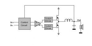
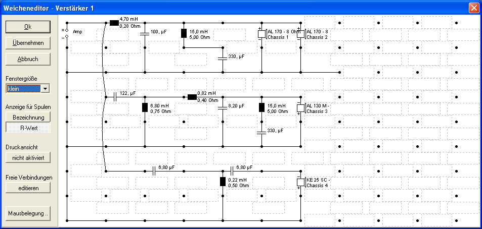
Coil placement will work. When i see the the value's of the parts then I assume you making your own filter.
I think you are making a big mistake by thinking that it is easy to make changes there.
Building speakers is not about how thick wood you use, how expensive loudspeaker driver you use, and how many watt's they have.
No it is all about making a good filter and making the right choices. Control the phase shift, isn't easy with a multi way.
And you shout test the end result with MLS measurement.
In this V20 experience design all things match very close the placement of the drivers and the filter design. Changing something there will have dramatical influence on the level of speaker loudness over the bandwidth. And the polar response of this loudspeaker.
I do not see impedance correction in your filter probably you do not understand what they are for. They are used because the filter wants to see a constant 4 Ohm load to have the right filter slope and phase.
Your asking open questions and that's good because you want to learn, and you probably think you under stand filter technique enough to do it your self.
At the filter that is where the speaker is made or spoiled. And it takes some time to understand where someone has made the wrong choices and what is the source of a difference. And then it is the art to solve that problem.
Visaton supports a free-ware program Boxsim you can edit the filter and see what the end result will bee. Then you are theoretical on the right way. Doesn't cost anything and the programm shows you what the problems are.
Here the link succes
Boxsim - Homepage
Attachments
Last edited:
You're right, I forgot a resistor. I noticed it after I uploaded the image.
BTW that design is outdated. It's from 2000.. This is the new one. I could also rotate the upper left coil by 90° Is that ok?
BTW that design is outdated. It's from 2000.. This is the new one. I could also rotate the upper left coil by 90° Is that ok?
An externally hosted image should be here but it was not working when we last tested it.
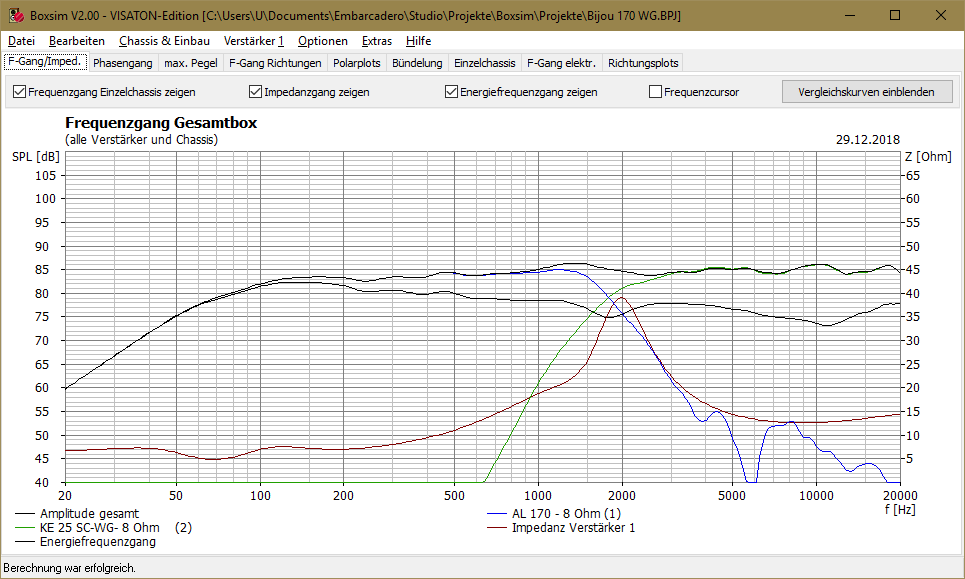
Boxsim uses:
1 the measured data and spl response of the visaton drivers.
2 the shape of the baffle and placement of the drivers
3 and the filter design ( this one you can change they way you want)
1

2

3
To calculate the radiated response.

1 the measured data and spl response of the visaton drivers.
2 the shape of the baffle and placement of the drivers
3 and the filter design ( this one you can change they way you want)
1
2
3
To calculate the radiated response.
Last edited:
You're right, I forgot a resistor. I noticed it after I uploaded the image.
BTW that design is outdated. It's from 2000.. This is the new one. I could also rotate the upper left coil by 90° Is that ok?
An externally hosted image should be here but it was not working when we last tested it.
Ok pipsk

What I said x-y-z or enough distance between them 10cm>
I would love to use that. But I don't understand a word German 🙁 I'm lost.Boxsim uses:
1 the measured data and spl response of the visaton drivers.
2 the shape of the baffle and placement of the drivers
3 and the filter design ( this one you can change they way you want)
1
2
3
To calculate the radiated response.
Then choose German in your language package at school.I would love to use that. But I don't understand a word German 🙁 I'm lost.
I can understand english and german enough to communicate 😀
I make many grammatical mistakes it doesn't matter people understand.
hello,
The above project (WMTWM) deceives in two very important aspects :
- the crossover doesn't reconstruct the phase correctly
- for realistic deep bass, you need 35Hz at - 3dB instead of 35Hz at -8 dB
The same money and effort can bring better results nowadays, in a domestic listening environment, and more compact.
Let us call this improved version a WMTMW Baekgaard arrangement :
a) you need to implement a Baekgaard crossover at 1700 Hz with Q=0,5. This is a phase accurate crossover (perfect reconstructed phase), however not very selective (2nd order only - quality drivers are thus mandatory), however delivering substantial inter-driver phase shifts in the overlap region (the WMTMW arrangement is thus mandatory).
b) a Baekgaard crossover is easy to implement both in active form and in passive form. You may thus mount your passive crossover in an external box for ensuring compatibility with an active crossover approach.
c) as you need a bass-reflex W section having a -3dB natural bandwith of 35 Hz to 3400 Hz, your W drivers shall not exceed 16 cm in diameter
d) in a domestic listening environment, two 16 cm diameter W drivers can deliver enough acoustic pressure, if they have a decent excursion like 4 mm
e) as you need a medium M section having a -3dB natural bandwith of 425 Hz to 6800 Hz, your M drivers can be 8 cm or 10 cm in diameter with low excursion and low power handling
f) as you need a tweeter section having a -3dB natural bandwith of 850 Hz to 15 kHz, a high quality 1 inch dome tweeter with built-in rear chamber would be the best choice, with decent power handling.
g) later on, for doubling the maximal sound pressure at 35Hz, you can build two or four W---W columns, same height as the main WMTMW colums, assisting them in the deep bass range. The crossover between the W---W column and WMTMW column would be active, 1st order at 120 Hz, for ensuring phase accuracy. You thus can use many same power amps in the 35 Hz to 120 Hz deep bass range.
Let me know if you agree the idea of the WMTMW Baekgaard arrangement. If yes, we'll base on the Visaton WMTMW design, select the drivers to be used, and tweak accordingly the dimensions of the wood panels.
Regards,
Steph
Last edited:
hello,
Let me know if you agree the idea of the WMTMW Baekgaard arrangement. If yes, we'll base on the Visaton WMTMW design, select the drivers to be used, and tweak accordingly the dimensions of the wood panels.
Regards,
Steph
He already ordered the parts Steph.
I find your idea interesting would be nice you would work out your proposal.
And simulate it in boxsim.
It is impossible to make something with this low prices.Do you have any idea on amp I could build to match those?
Yamaha RX-497 od 252,00 € - Heureka.sk
An externally hosted image should be here but it was not working when we last tested it.
to Helmuth. I just started a new thread about the WMTMW Baekgaard here : http://www.diyaudio.com/forums/multi-way/174276-wmtmw-baekgaard.html#post2314251
Damping
Walls universally applicable anti-drumming and insulation material
Standing waves between the panels inside the box.Merfocell Burl foam (50 mm)
or this kind of stuf.

Or carpet.

To damp the volume use loose sheep-wool. Or a synthetic kind of wool. No wool between BR-pipe and woofer these two need a good coupling to work fine.
The wool needs to be lose not pushed inside, when it is lose the cabinet will be theoretical bigger volume for the driver. When it is to dense to volume of the box will decrease the opposite of what it is meant for.
An externally hosted image should be here but it was not working when we last tested it.
Walls universally applicable anti-drumming and insulation material
An externally hosted image should be here but it was not working when we last tested it.
Standing waves between the panels inside the box.Merfocell Burl foam (50 mm)
An externally hosted image should be here but it was not working when we last tested it.
An externally hosted image should be here but it was not working when we last tested it.
or this kind of stuf.
An externally hosted image should be here but it was not working when we last tested it.
Or carpet.
To damp the volume use loose sheep-wool. Or a synthetic kind of wool. No wool between BR-pipe and woofer these two need a good coupling to work fine.
The wool needs to be lose not pushed inside, when it is lose the cabinet will be theoretical bigger volume for the driver. When it is to dense to volume of the box will decrease the opposite of what it is meant for.
An externally hosted image should be here but it was not working when we last tested it.
- Status
- Not open for further replies.
- Home
- Loudspeakers
- Multi-Way
- Will you help a newcomer with his first multi-way project?