Oh! 🙂 Mike! I known your method .IF, you simulate symmetry circuit, adjusting offset is a hard thing
Thanh!
What is the summary of your Hawksford thread? Is error correction a good thing? You got masters there, like Pass, Steven, etc.
What is the summary of your Hawksford thread? Is error correction a good thing? You got masters there, like Pass, Steven, etc.
lumanauw said:Hi, Mike,
Please do so in Sims. I also want to look at the effect of 220K parrarel with Cdom. I have found one commercial unit (quite expensive) that do this.
I think it has to do with gain-bandwith product. Make amp with high gain, but low bandwith or we can create moderate gain but have wide bandwith.
Hi lumanauw !
I tried a little with these resistors, and they do have a great impact
on openloopbandwidth. Without global feedback, the bandwidth
got 5 times better. In my ckt i used 1Mohm, with these resistors
i had nearly the same bandwidth as with 220k, but not that big loss
in gain. It's like always... The less gain, the more bandwidth. :-(
But the overallperformance of the amp didn't get better, because
with global feedback i had still more gain at 20khz without the
resistors than with them.
Measurements didn't get better, but listening has still to be done...
It seems that for an amp with global feedback, you can't just look
at openloopbandwidth. Maybe my method i told to thanh is not
correct. I've read in another thread that Dr Leach said once that
openloop bandwidth is not that important, that's its the "gain-bandwidth"
that matters. But Nelson Pass does not agree. So its up to my ears
to verify what's better for me.
Mike
Hi, Mike,
Yes, calculations or SIMS doesn't always give a clue about audible sound. We just have to listening-test for knowing.
Lets see 2 amps that have very different gain/bandwith and both have marvelous sound. They are Aleph (low OL gain) and AKSA (high OL gain). So what is making good sound?
Thanh!
What sims sweep are you attaching? For error correction or other sch? They seems not have pattern.
Leach sai that "TIM cannot occur if the open-loop bandwidth is greater than the signal bandwidth"I've read in another thread that Dr Leach said once that
openloop bandwidth is not that important, that's its the "gain-bandwidth"
that matters
http://users.ece.gatech.edu/~mleach/lowtim/bckgrnd.html
thanh said:
Leach sai that "TIM cannot occur if the open-loop bandwidth is greater than the signal bandwidth"
http://users.ece.gatech.edu/~mleach/lowtim/bckgrnd.html
Hi thanh,
Thanks for the interesting link !
It inspired me to do some "mesurements" in spice, to compare
my amp with the leach. Of course this comparison is not the best,
the amps differ much in power. (120Watt into 8 ohm to 55Watt into 4ohm)
The results:
Phaseshift at 20khz:
Mine has 1.85° before coil, and 10.5° after coil, maybe i should
reduce the coil ? (It's purpose is to protect against capacitive loads)
Leach is 8.8°
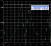
Bandwidth:
Mine has a drop from 33.394db to 33.287db. That's about the
same value like the Leach (~-0.1db @ 20khz)
(before coil the drop is ~0)
IMD:
Mine has ~0.0013% at full power, Leach is about 0.0059% at
similar powerlevels. (But into 8 ohm)
THD:
The Leach has an increase of factor ~48 over the bandwidth up to
20khz, this seems pretty much to me ?
Mine has about factor 7. (okay, mine is high OL-gain)
(at 1khz full power mine has ~0.0003%)
Now, i am not sure how representive this is, as the Leach values
are from realworld measurements, but i think that my small circuit
still has a lot of potential...
Mike (now some kind of proud...)
Mike! How can I do to simulate TIM in orcad?
Indeed, I don't understand about TIM completely.
With high degeneration resistor, the amp will get more distortion but more stable. My amp oscillated with 1ohm ,
Indeed, I don't understand about TIM completely.
With high degeneration resistor, the amp will get more distortion but more stable. My amp oscillated with 1ohm ,
thanh said:... With high degeneration resistor, the amp will get more distortion but more stable. My amp oscillated with 1ohm ,
Hi thanh
The higher is the degeneration, the lower is the open loop gain of the amp, thus the lower is the feedback factor. In a standard Negative feedback amp, the distortion in open loop is reduced by the amount of the feedback factor. If you amp oscillate with 1 ohm (thus no degeneration) it means that the open loop gain is too high at high frequency. You need to find the "proper" degeneration resistors value for your amp to have reasonable THD and TIM. Therefore, it is a compromise based on your objective. You can not maximize both THD amd TIM at the same time (based on the concept of high degeneration resistors to reduce TIM).
Fab
TIM is like too much treble. TIM is not always bad, at least that's what I learn in PassDIY and Leach paper (http://www.diyaudio.com/forums/showthread.php?s=&threadid=30103&highlight=)
Aha,
That might explain what went wrong with my previous amp, it
had too much treble, but bandwidth seemed ok. The Sound
was annoying, it didn't make fun to listen to.
to thanh:
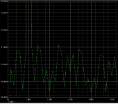
I used the model described by Dr.Leach, a combination of a 60hz
and 4khz signal with a ratio of 4:1. I mixed the freqs with low ohmic
resistors. The transient needs a window of 50ms.
Then i examined the "harmonics" around the 4khz. I summed them
all, and calculated a ratio to the 4khz signal.
Mike
That might explain what went wrong with my previous amp, it
had too much treble, but bandwidth seemed ok. The Sound
was annoying, it didn't make fun to listen to.
to thanh:
I used the model described by Dr.Leach, a combination of a 60hz
and 4khz signal with a ratio of 4:1. I mixed the freqs with low ohmic
resistors. The transient needs a window of 50ms.
Then i examined the "harmonics" around the 4khz. I summed them
all, and calculated a ratio to the 4khz signal.
Mike
I use a balanced input stage .So how can I put a passive filter such as slowhands?
Is "Lead compemsation" a so-called "feedforward " by Leach?
Why don't we continue to disscuss about lumanuaw's idea?😀
Is "Lead compemsation" a so-called "feedforward " by Leach?
Why don't we continue to disscuss about lumanuaw's idea?😀
I just found something in my design. In my original design, the PNP is sitting on -1V2 (adjusted by VR or servo)
I dont know what happened, but when I change the reference voltage (put the base of PNP directly to ground, and make the NPN base sits on +1V2 with help of input capacitors + 47k to the wiper of the adjusting VR), it sounds much better.
Why is that? Is it obvious in SIMS?
I dont know what happened, but when I change the reference voltage (put the base of PNP directly to ground, and make the NPN base sits on +1V2 with help of input capacitors + 47k to the wiper of the adjusting VR), it sounds much better.
Why is that? Is it obvious in SIMS?
Hi lumanauw !
Sorry that i didn't simulate your topology earlier...
Let me guess, you now have much clearer sound, better details
and trebles ?
The ~50k resistance for feeding the npn was to high, you hadn't
enough current to the base, this limited the bandwidth to -3db @ 60khz.
Now the base is connected to ground, via 1 kohm or less. This boosts
bandwidth up to -3db @ 237 khz. Now the bandwidth degenerates far
above 20 khz, with the resistance it began at 10khz.
You can compensate this by adding a cap (to ground) to the base of
the pnp. This modification enhances the bandwidth by ~factor 5 !
The values are not accurate, i didn't simulate exactly your ckt,
(had already done some mods) but the effect should be the same.
Mike
Yup, you got that Mike. 😀 But I dont follow your explenation. Could you give it a simple words?Let me guess, you now have much clearer sound, better details
I tought I just alter the reference voltage, from -1V2 in the PNP, now to +1V2 in the NPN (input) and leave the PNP base to ground.
Because the input-feedback system is at virtual ground (inverting output power amp), the impedance of input should be about the same, shouldn't it?
Yes, the inputimpedance keeps. I talk about the pnp, which is
supplying a constant voltage to the emitter of the npn.
Because of the 100k-pot you have a resistance of ~50kohm
to the base of the pnp. By connecting this base to ground, you
removed this impedance. With this impedance the voltage seemed
to be not constant enough, especially for higher freqs. That's why
a cap can solve/reduce this problem.
Mike
Hi, Mike,
You are right. Thanks for the explenation. Which is better to put reference voltage in pnp or npn (--->pnp+cap like you suggested)?
The harmonics is not canceled, which is the aim. Do you have any other suggestion for this amp tobe nice sounding one?
You are right. Thanks for the explenation. Which is better to put reference voltage in pnp or npn (--->pnp+cap like you suggested)?
The harmonics is not canceled, which is the aim. Do you have any other suggestion for this amp tobe nice sounding one?
- Status
- Not open for further replies.
- Home
- Amplifiers
- Solid State
- Will this work as audio amplifier?