lumanauw said:
My design has already NFB, with 100K feedback and 1K input R, hasn't it?
Bad output stage, eh?😀 How about parrareling the output device, will it help?
or do you have simpler solution for the problem you found, but please not so difficult as putting Hawksford error correction.
Damping factor is a dissaster. What is the sound of audio amp with dissaster damping factor? Bad bass?
No, your design is a classical feedback. NFB means No FeedBack.
This means you have a 1cap + 1 resistor connected to the input,
nothing else. NFB is openloop !
Paralelling output devices reduces the effect, but does not solve it.
The sound of bad dampingfactor is bad bass, and bad frequency
response. As a speaker does not have a linear impedance, the
frequencyresponse will show the same curves. Bad bass means
too much of it and totally uncontrolled/unprecise. It can destroy
you speaker !
Mike
lumanauw said:...
Mr. Curl and Mr.Borbely likes to use servo. Maybe this is because the DC drift/temperature caused is too big like you observed? Inspite of its DC offset weakness, they always use Jfet for input differential. Maybe the sound is too good so they dont want to change to bipolar input differential?
...
lumanauw
Mr Borbely uses matched N and P jfet pairs for diff input. It must use servo since there is no DC blocking caps for input and feedback loop (at least in the design I saw). You may be right about the sound of jfet since Mr Borbely switched from bjt to jfet. I have already built a preamp with symetrical jfet diff input and then compared it with the same design except for the symetrical bjt diff input (with added ccs) and the difference in sound was obvious. The jfet input preamp was more "detailed" (I know I am always saying the same thing...).
Fab
Sorry, wrong assumption about NFB. How to maintain DC offset? Servo? My servo design is not working. How to make servo for this design?
FAB,
I just experimenting with CFP-Jfet/Bipolar differential (like Mike use) and single mosfet differential (IRF510). The sound of mosfet differential have "something" that sounds better. You should try this.
FAB,
I just experimenting with CFP-Jfet/Bipolar differential (like Mike use) and single mosfet differential (IRF510). The sound of mosfet differential have "something" that sounds better. You should try this.
Don't give up ! 🙂
Hi All !
I'am really intrested about this thread !!!
I also have a project to build an amp with these
solutions like CFP stages, cascodes and so an...
I attach a version of my design, its based on
peufru-s site and on memory distortions.
Its only a copy-paste design at this point, but
soon i will built it, and make some listening test !
I readed a lot of docs about this kind of solutions in
power amps but there is a lot of confusing oppinion.
Please write your opinion about my amp !
For example this kind of CCS is the better or the
cascoded type, like at peufru-s site ?
And imho it would be an intresting test to try out
drive your test-amps in inverting mode with high
values of the feedback resistors, ~ 1Meg and 33k...
And i'am waiting impatiently for the real listening
tests about MikeB's symmetrical CFP input stage too ! 🙂
Thanx a lot !
Cortez
(NFB ?= Negative FB)
Attachments

Hi lumanauw !
I was checking the circuit for the possibility only, and at least the
input/vas shows a lot of potential. I think it will need a DC-servo,
Simply adjusting with a pot might be to unstable, but possible with
a openloopgain of only 1:40. But DC-servo shouldn't be to difficult,
maybe possible with a single jfet + some "small" caps ?
And it seems that with NFB a standard outputstage is useless.
Last night i finished my symetrical bjt-design, and i can assure that
jfets sound very different. (they are very bright/detailed)
I was not able to make real listeningtests, the new amp has a very
unstable VAS-biasing. (greetings to thanh...) Symetry with cfp seems
difficult. But maybe i miswired something. (hopefully)
Every ~30secs the bias get's that low, that the outputstage drops
below class-b, giving audible crossover.
(vas-current changes periodically between 100uA and 2mA).
But the difference was still audible immediately. (soft but clear)
I will "debug" this evening... 😀
I had a symetrical jfet-design before, it showed the same brightness
and details as the asymetrical. But this one had some strange problems,
it just didn't make fun to listen to... (never found out why)
I believe that the CFP-jfet/bjt diffamp is really interesting.
Mike
Re: Don't give up ! 🙂
Welcome Cortez !
I am not familiar with the peufeu, but your design looks good to me.
The ccs-driven buffer after vas is always good... But i tried in sims,
a "normal" VAS followed by a classA-predriver performs better.
The classA-predriver seems to put nearly no load to the vas.
The diode at the emitter of vasinput seems suspect to me.
Yes, i am waiting impatiently for the real listening too, but i have to
solve this instability before.
NFB = negative feedback, oops !
Maybe NoGFB ? 😀
Mike
Cortez said:Hi All !
Please write your opinion about my amp !
For example this kind of CCS is the better or the
cascoded type, like at peufru-s site ?
And i'am waiting impatiently for the real listening
tests about MikeB's symmetrical CFP input stage too ! 🙂
(NFB ?= Negative FB)
Welcome Cortez !
I am not familiar with the peufeu, but your design looks good to me.
The ccs-driven buffer after vas is always good... But i tried in sims,
a "normal" VAS followed by a classA-predriver performs better.
The classA-predriver seems to put nearly no load to the vas.
The diode at the emitter of vasinput seems suspect to me.
Yes, i am waiting impatiently for the real listening too, but i have to
solve this instability before.
NFB = negative feedback, oops !
Maybe NoGFB ? 😀
Mike
Hi !
> Welcome Cortez !
Thanks ! 🙂
> I am not familiar with the peufeu, but your design looks good to me.
And what's your opinion about cascoded CCS vs. this type by my amp ?
Maybe the cascoded one gives better results (speed and accuracy) ?
Or maybe the thermal-distortion is less with cascoded CCS ?
Have anyone either simus or real-life experiences about it ?
> The ccs-driven buffer after vas is always good... But i tried in sims,
> a "normal" VAS followed by a classA-predriver performs better.
Do U mean, a normal triple-darlington like in the leachamp instead the
CFP output stage is better ? Do you tried already a CFP output like this ?
An other thing what i cant decide, that an emitterfollwer before the VAS
is the better, or a buffer stage after it ? Eventually the triple-darlington
is also like a buffered VAS, isnt ? (Just symmetrical and woks on classA 🙂
> The diode at the emitter of vasinput seems suspect to me.
Just an idea (against saturation), i'll test the amp with and without it.
These was final conclusions, that i read recently here at diyaudio:
- Cascoding the diff current source and VAS current source show by far the biggest improvements.
Cascoding the VAS shows a much smaller improvement.
- Emitter follower between diff amp and VAS shows second best improvement.
Opposite sex than VAS device being slightly better than same sex, and about the same as a super pair VAS.
- CFP configuration for the diff amp trannies also improve things slightly.
Secondary effect is that DC offset decreases dramatically, due to higher current gain,
thus loading feedback network and input bias resistor less. Probably linearises the diff amp quite a bit.
- Use emitter degeneration resistors !
- Install cascode stages at both collectors !
Do not refer the cascodes to the emitters (as normally),
but to the node where the two emitter resistors and the current source join.
- Chose the bias for the cascodes so that Uce of the LTP transistors is the same
as the voltage across the emitter degeneration resistors.
- The simulation with all these implemented, shows 2nd harmonic about 122 dB down at 10 KHz,
after that about 130 dB down for ALL harmonics, odd and even, up to 10th.
So i tried to design my amp based on these advices blindly.
(Hope they are verities...!!! ;-)
Cortez
>Do U mean, a normal triple-darlington like in the leachamp instead the
>CFP output stage is better ? Do you tried already a CFP output like this ?
>An other thing what i cant decide, that an emitterfollwer before the VAS
>is the better, or a buffer stage after it ? Eventually the triple-darlington
>is also like a buffered VAS, isnt ? (Just symmetrical and woks on classA 🙂
No, CFP output stage is not bad, but not most stable, and can get
difficult for higher freqs if not classA. (crossover and more)
I tried cfp-output, but different to yours. It sounded great !
hmm, the predriver is simply a buffer after vas, and is completely
different to an emitterfollower before vas. But both can do a great job.
But to many buffers slow down the whole ckt...
ClassA means here, the current does not change much. I think because
of the two bases from the buffer connected to the vas, the currents
into these bases cancel out each other because of their signs.
This would be some "noloadatall" to the vas. Of course it's not
that simple, but this could be the reason, why the symetrical
predriver outperforms the ccs-loaded buffer.
This predriver is a good companion to a cfp-output.
Mike
> No, CFP output stage is not bad, but not most stable, and can get
> difficult for higher freqs if not classA. (crossover and more)
Intresting, i saw a lot of ckt where the output stage was CFP
and they doesnt had any stability problems.
> I tried cfp-output, but different to yours. It sounded great !
What can be else like by my design ? Its a simle Compleneter
Darlington configuration. What was the difference in your amp ?
And in your amp why dont U use CFP now ?
Cause of these instability issues ?
> hmm, the predriver is simply a buffer after vas, and is completely
> different to an emitterfollower before vas. But both can do a great job.
> But to many buffers slow down the whole ckt...
Yess, and therfore i cant decide, which one is the better... 🙂
What do you think about differential VAS ?
Or a current mirrored VAS.
Like in the Bi240 amp at ampslab:
http://www.ampslab.com/Images/bi240_schema.gif
Or in a russian design here:
http://www.arky.ru/audio/shem/hppa/hppa.htm
What can be the benefit of these solutions ?
Mike, after your experiences the FETs are better,
then the BJTs in the input stage in a CFP ?
And if U have time and ambitions, dont U would like to
try out the inverted mode with high feedback-resistors ?
At values 1Meg/33k a 2-3uF cap is enough, if U use they
at the input. I tried out this by a basic design
classical classAB amplifier, and it improved the sound.
The only problem was the DC (4-500mV), cause i dont used
any DC-servo.
As my amps are already high gain, the normal CFP made them
unstable. But the mainreason i don't use them now, is that i
try to build an amp with very low distortions on high freqs.
And cfp-output tends to crossoverdistortions on high freqs.
Also, with cfp you have to be careful with clipping.
I didnt connect the emitters of the drivers directly to the collectors
of the outputdevices, i connected them with 22ohm to the output.
This was much more stable. (but this one was with mosfets)
I choose the predriver, because with it you can use a lowcurrent-
vas with small signaltransistors, no longer needing the buffer
before vas.
I am not sure about differential vas, i believe they produce more
3rd harmonics. But the ampslab version uses a currentmirror, this
should eliminate this problem.
I cant say if jfets sounds better then bjts in the inputstage (cfp'd),
i am still researching. I have the feeling that jfets sound too bright.
About the inverted mode, i will try if i have some time left...
Mike
If you want cascode & push-pull vas why not:
In addition to being easier to read because I used .gif (or .png; please, please don’t use jpg for schematics), I think the diff pair cascoding shown here is simpler that the “mike.jpg” schematic in post #135 – ac bootstrapping the cascodes to the input common mode V can help too
I did throw in the kitchen sink on the vas section though; 6 power mosfet source followers are going to be a fairly large capacitive load so I think a large current multiplication of the diff pair’s current is in order ( = complemetary darlington vas)
I’ve also shown a compound cascode with a Baxandall Super Pair for the cascode transistors, the sim seems to be happy with the C2,3 bypass (DC bootstraped R16,17) but anyone embarking on cascodes of any flavor should be good at rf debugging
The vas output is the collectors of Q11,12 – I’ve left out the output stage V bias and was playing with the load Z and V4 ac source to get an idea of the current source output impedance and linearity (I don’t like the idea of throwing away gain by adding shunt Z to ground in the amp though)
The sim seems happy putting out +/- 150 mA with the distortion looking like the classic diff pair tanh spectrum (even harmonics supressed to ~ = amplitude of odds), pretty independent of frequency, looks the same at 2K and 20KHz
(default LtSpice zeners top out at 15 V, the BD139/140 models are from fairchild)
LtSpice file, change .txt to .asc
> And cfp-output tends to crossoverdistortions on high freqs.
> Also, with cfp you have to be careful with clipping.
I guess i'll try both CFP and triple-darlington to test the sound of them...
> I choose the predriver, because with it you can use a lowcurrent-
> vas with small signaltransistors, no longer needing the buffer
> before vas.
Yes, thats correct, and indeed this should be the right way..
> I am not sure about differential vas, i believe they produce more
> 3rd harmonics. But the ampslab version uses a currentmirror, this
> should eliminate this problem.
Ohh, there is a lot of thing that confuse me... 🙂
This alternative should be also tested both with simus and listening tests.
> About the inverted mode, i will try if i have some time left...
Thx, i'am curious about this test ! 🙂
Hi, all,
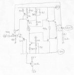
The main idea of this thread is this design. I was exploring, what its like to have a SS amp that do not cancel harmonics. So I dont use differential at front stage, but using configuration of Q1 and Q2 to advoid cancelation. It works, if base of Q2 is held by -1V2, it will perform signal depended current path, that feed the folded cascode--->who drives the final stage. Folded cascode VAS doesn't have gain, it just level-shift the current produced by Q1-Q2 to drive final stages.
The main idea of this thread is this design. I was exploring, what its like to have a SS amp that do not cancel harmonics. So I dont use differential at front stage, but using configuration of Q1 and Q2 to advoid cancelation. It works, if base of Q2 is held by -1V2, it will perform signal depended current path, that feed the folded cascode--->who drives the final stage. Folded cascode VAS doesn't have gain, it just level-shift the current produced by Q1-Q2 to drive final stages.
Attachments
What ?
I have my own design, i will soon build it.
And will write the results here of corse.
MikeB !
Something new result ?
I have my own design, i will soon build it.
And will write the results here of corse.
MikeB !
Something new result ?
- Status
- Not open for further replies.
- Home
- Amplifiers
- Solid State
- Will this work as audio amplifier?