Hi, Mike,
How about folded cascode VAS? Is it creating the same thing as VAS in post #1?
If 2nd harmonic is just "not detectable" instead of giving "nice sound", what is really happening in SET tube? There is measurement comparison with SET tube amp (CARY 300SEI) with "very good figures" amp. SET amp gives very bad measurement result.
But in listening test, this SET excells the other amp. Every test subject says the same. If this is not caused by 2nd harmonic, what cause this SET sound "NICE"?
Are you simulating ordinary VAS or my differential VAS in post #1?I did some checkings on VAS with Spice, it seems that the VAS mainly creates 2nd harmonics, but i don't know if this
is still so if the transistors are matched. Cascoding the VAS
had a very big increase in qualitity
How about folded cascode VAS? Is it creating the same thing as VAS in post #1?
Interesting. So 2nd harmonic is not adding "Niceness". It's just not detectable.Yes, odd harmonics are agony... and the human ear is extremely sensitive to them. I experimented a little, add 3% 3rd harmonic to music (done with software), and you instantly puke, add 3% 2nd harmonic, and you wonder if there really is a difference !
Yeah, thats what they say. Measurement figures doesn't give a clue about how a power amp sound.But this means that simple THD-measurements are useless to describe the soundquality of an amp. (Not a new discovery at all...)
If 2nd harmonic is just "not detectable" instead of giving "nice sound", what is really happening in SET tube? There is measurement comparison with SET tube amp (CARY 300SEI) with "very good figures" amp. SET amp gives very bad measurement result.
But in listening test, this SET excells the other amp. Every test subject says the same. If this is not caused by 2nd harmonic, what cause this SET sound "NICE"?
IT WORKS
Just finished prototype of my own idea in post #1. IT WORKS as audio power amp.
BUT, the servo type doesn't work. It seems the voltages in the 1M resistors drop so much, that the servo cannot see what happens in the output stage. Maybe other kind of servo will work for this, but not the servo in #1.
The one that works is the conventional VR type. I put VR in base of Q2, to set the reference voltage for Q1. (100k, left to -15, right to+15, CT to base of Q2)---> it needs manual adjustment. I'm afraid of DC offset drifting with heat, but from 1/2 hour, it looks steady.
I'm glad that this Q1-Q2 arrangement can made a signal depended current path. So there is another option for this front end current switch besides differential pair.
Q1 and Q2 works as 1 way current path. Differential works as intersection of 3 current path.
If differential pair cancels 2nd harmonic, hopefully this 1 way current path doesn't. Maybe can lead to "good sounding amp" not "good measurement amp"?
Hi lumanauw,
I did these checks on ordinary VAS, i checked symetrical and
asymetrical design. The symetrical design has 2 times the gain,
which is logical. I will check your design this evening...
"So 2nd harmonic is not adding "Niceness". It's just not detectable."
On a PCspeaker, yes. I have to make this test again, with the PC
connected to the Stereo... Maybe my ears are not good enough
for a representive test. (This i Psychoacoustic, varies between
different people) Maybe it's not only 2nd harmonic, but a
specific combination of 2nd & 4th ?
Because i want to know this, i will build a SE-ClassA, not tube,
i am not familiar with these devices.
Does anybody know if the jFet-model in Spice is accurate ?
Because if it is, it would mean that jFets have a far better
transfercurve then BJTs (Audiophile !) In Spice they produce
nearly no 3rd order, only 2nd order, and no highorder harmonics at all. If it is, i would make a SE-Amp nearly FET-only.
Mike
Referring to Post 1:
Your servo circuit can't work this way !
You don't have a reference for Q1 (resistor to ground), or your reference via Q2 is not 0V but 2*0.7V (check V at the base of Q1) Your DC-servo is in the inverting mode ?
I think that Q1 must "run" with more current, about 1 or 2 mA.
Your design is a CFP input, folded cascode VAS.
Maybe you can post your new design, or at least your new Q1 reference to see what's wrong ?
For CFP:
Have a look here ...
Post 42
And graphs here ...
Post 46
My actual design is a little different but it's sounds music !
Output stage not yet choose ...
What about MOSFETs for front end. Like Passlab uses IRF610 or IRF9610. Are they producing the same harmonics as Jfets?In Spice they produce nearly no 3rd order, only 2nd order, and no highorder harmonics at all.
Well, it is not working, but why?Your servo circuit can't work this way !
I'm aware that Q1 must have ground reference. Look at post #7. This design is for DC coupled. For AC/Capacitor coupled, we must add R#3 to set ground in Q1.You don't have a reference for Q1 (resistor to ground), or your reference via Q2 is not 0V but 2*0.7V (check V at the base of Q1)
It has tobe inverting to work. You can trace the current, like what happens if the output is too positive.Your DC-servo is in the inverting mode ?
Yes, you are right. Q1+Q3+25k resistor can be seen as 1 component, CFP transistor. They can be replaced with just one transistor, if you like. I'm still confused in this CFP configuration, what is the good value to be flowing in each transistor. FAB suggested 1/4 of total.I think that Q1 must "run" with more current, about 1 or 2 mA. Your design is a CFP input, folded cascode VAS.
lumanauw said:
What about MOSFETs for front end. Like Passlab uses IRF610 or IRF9610. Are they producing the same harmonics as Jfets?
In Spice they show the same behaviour, seems FET = FET
The MOSFETs have the advantage of having a much higher
max voltage (>100v), while jFets are up to ~40v.
But jFets like sk170 have a much higher gain, nearly as high
as a BJT.
I checked the behaviour of a diffamp fed with a plain resistor
from a low railvoltage. The 3rd harmonics nearly stay the same,
but the 2nd harmonic explode. (in my testcase from 10nV to 1mV,
tested with jFETs)
Mike
Hi, lumanauw.
Differential mode cancels 2nd harmonic only if you sum the ouput signal from the collectors of the differential pair. In your case, it's just a Common Emitter in CFP config.
For your CFP, the current in Q1, depends on what you plan for this stage, it depends of your choice for Q1/Q2 and their Hfe. You can start with 2mA (1/10 of Ic Q2).
Sorry about DC-Servo ! When i wrote this, on last post, i forgot that the output is "out-phase".
If you want to go at the end of your idea, maybe you can fix the problem with 2 diodes in series between the base of Q2 and the 1k from the IC, you need two resistors (10k) between the diodes and +V / -V to set the current (5mA). In this way with a trim between these diodes and the center to the base of Q2 you can adjust the offset. The op-amp in this circuit will "always go" for 0V at his output (0V reference). If you prefer, you can set the + input of the op amp at -2*Vbe.
Sorry, my English is bad.
Again, sorry my English is bad.
I found something interesting. I played CD of classic guitar instrument. The sound of the guitar seems have more "vibration" and "depth" than usually. Is this mean the "nice 2nd harmonic" is added to the amp (or at least not canceled as in ordinary 3 stages amp)?
Trying to get closer to the destination---->Nice sounding SS amp. I've heard SET amp, Manley 300B. It sounds nice. But for me too small power.
Is this mean that if we take only 1 output from differential collector, it wont cancel 2nd harmonic? Aleph take only 1 output from the differential. Differential in Aleph doesn't cancel 2nd harmonics?Differential mode cancels 2nd harmonic only if you sum the ouput signal from the collectors of the differential pair. In your case, it's just a Common Emitter in CFP config.
Again, sorry my English is bad.
I dont get it. Could you draw a picture of your idea?If you want to go at the end of your idea, maybe you can fix the problem with 2 diodes in series between the base of Q2 and the 1k from the IC, you need two resistors (10k) between the diodes and +V / -V to set the current (5mA). In this way with a trim between these diodes and the center to the base of Q2 you can adjust the offset. The op-amp in this circuit will "always go" for 0V at his output (0V reference). If you prefer, you can set the + input of the op amp at -2*Vbe.
I found something interesting. I played CD of classic guitar instrument. The sound of the guitar seems have more "vibration" and "depth" than usually. Is this mean the "nice 2nd harmonic" is added to the amp (or at least not canceled as in ordinary 3 stages amp)?
Trying to get closer to the destination---->Nice sounding SS amp. I've heard SET amp, Manley 300B. It sounds nice. But for me too small power.
OOOH! Are you sure? Which circuit did you simulated? I'm using Orcad 9.2.My sim says that single ended Jfet produces 2nd ,3rd very much and a little high order harmonics .In Spice they produce
nearly no 3rd order, only 2nd order, and no highorder harmonics at all. If it is, i would make a SE-Amp nearly FET-only.
I think Jfet with no source resistor only produces 2nd but in the real world Jfet alway is wired with a resistor
http://www.its.caltech.edu/~musiclab/feedback-paper-crobat.pdf
Hi, lumanauw.
I got time to check your circuit, and tune it.
For the moment, forget my last post, it was just some design advises.
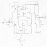
I think this general diagram should be ok.
R8 in my schematic, is just for simulation, remove it and insert your output stage bias between I3 and Q4.
You can replace I1 by a resistor between base and emitter of Q3 about 330 to 680 Ohms, for 1-2 mA of current for Q3.
I use OPA 627 or AD 743 for DC-servo but you can do it with an TL0701.
A small amount of local feedback is provided by R3,R4,R5, for stability and linearisation.
THD 2 about 1%, is really not important for the quality of sound, most significant are the higher order harmonics 5,6,7 etc... even at very low levels.
I got time to check your circuit, and tune it.
For the moment, forget my last post, it was just some design advises.
I think this general diagram should be ok.
R8 in my schematic, is just for simulation, remove it and insert your output stage bias between I3 and Q4.
You can replace I1 by a resistor between base and emitter of Q3 about 330 to 680 Ohms, for 1-2 mA of current for Q3.
I use OPA 627 or AD 743 for DC-servo but you can do it with an TL0701.
A small amount of local feedback is provided by R3,R4,R5, for stability and linearisation.
THD 2 about 1%, is really not important for the quality of sound, most significant are the higher order harmonics 5,6,7 etc... even at very low levels.
An externally hosted image should be here but it was not working when we last tested it.
smallthanh said:
OOOH! Are you sure? Which circuit did you simulated? I'm using Orcad 9.2.My sim says that single ended Jfet produces 2nd ,3rd very much and a little high order harmonics .
I think Jfet with no source resistor only produces 2nd but in the real world Jfet alway is wired with a resistor
http://www.its.caltech.edu/~musiclab/feedback-paper-crobat.pdf
???
I think i use some 9.1 ...
Which jFet did you use ? I mainly use the sk170.
I use the jFets without sourceresistor, works fine. (In real world)
With singleended, i had nearly no 3rd harmonic, about <0.5% of
2nd, and for high order i have to zoom far in.
A diffamp with jFets showed 3rd Harmonic, 2nd completely canceled
out, and other barely existent.
And all harmonics were way below a BJT, really extreme with
large voltage/current-swings.
When using a ccs, the BJTs seems better, but this does not work
for voltageamplification. (But perfect for buffer)
If only jFets would be cheaper, matching these gets really expensive !
(i paid 49cent per sk170, only 4cent per bc546b/556b)
Mike
Hi, Dad,
I think you forgot to put feedback resistor to base of Q1.
Please write the SIMS result that you find. Especially the harmonics figures, and if there is anything strange with this cct.
I think you forgot to put feedback resistor to base of Q1.
Please write the SIMS result that you find. Especially the harmonics figures, and if there is anything strange with this cct.
I will send you tomorrow simulation results, but it's mean nothing for sound quality.
Try it ! In real world !
I think that you should better keep the R8 resistor that sets the gain, and avoid feedback, but it's something you can test (listen).
Did you bilt it ?
Try it ! In real world !
I think that you should better keep the R8 resistor that sets the gain, and avoid feedback, but it's something you can test (listen).
Did you bilt it ?
FFT plot for 1v AC input, 20 V peak to peak Output.
With no feedback, and R8=1k, if you need more gain increase R8.
Build it, and keep me inform about listening tests.
With no feedback, and R8=1k, if you need more gain increase R8.
Build it, and keep me inform about listening tests.
An externally hosted image should be here but it was not working when we last tested it.
Hi, Dad,
You just indicating one interesting point. Is this design can be made non-feedback? I think the gain is low enough for non-feedback, and needs only other R adjustment. Loading it with R8 maybe a good candidate for non-feedback type.
In your drawings, what is the purpose of R3,R4,R5?
Thank you for simulating it and generate FFT. But what is the interpretation of lumanov.cir? Is it like ordinary power amp, or differs?
Also, do you find problem with stability in SIMS?
Yes, I've built it look at post#22. In my prototype, the servo type doesnt work. The offset is about 7V. But when I replace the servo with manual adjustment VR, it works.Try it ! In real world !
Look at post #28Build it, and keep me inform about listening tests
If we make it without R8 (you said its for sim only), and put output stage instead, it will need feedback resistor, wont it?With no feedback, and R8=1k, if you need more gain increase R8.
You just indicating one interesting point. Is this design can be made non-feedback? I think the gain is low enough for non-feedback, and needs only other R adjustment. Loading it with R8 maybe a good candidate for non-feedback type.
In your drawings, what is the purpose of R3,R4,R5?
Thank you for simulating it and generate FFT. But what is the interpretation of lumanov.cir? Is it like ordinary power amp, or differs?
Also, do you find problem with stability in SIMS?
Mike! I use 2SJ109
You are using orcad 9.1,aren't you? Can you post your circuit?
Indeed,I'm not good at designing FET.
Look at Dad's simulation, 3rd harmonic is quite high. Ok! high order harmonics are still alive
A ideal Jfet has no juntion resistors .But in the real world and in simulating sofware Jfet has a juntion resistor
And IMD ?But this means that
simple THD-measurements are useless to describe the soundquality
of an amp. (Not a new discovery at all...)
I like zero distortion.I think HIFI is high fidelity .This means you can't regconize the difference of sound of amp and singing
Hi thanh !
At moment i'm at work, but as soon as possible i can post some
schematic. But maybe we should use a separate thread ?
With junctionresistor you mean a virtual resistance inside the
device ? I think in Dad's simulation the harmonics are typical for
an asymetrical bjt-design with moderate feedback. But still 3rd
harmonic is only ~10% of 2nd. Not bad, i think !
It seems, that low TIM is important, but as representive as THD.
Of course, an Amp with no THD/TIM would be ideal, but unrealistic.
So, we need compromises...
Take a look at http://www.gedlee.com/distortion_perception.htm
If i understand "masking" correct (damned psychoacoustic), it
means that if you have enough 2nd harmonic, the 3rd gets
simply inaudible ! lumanauw should really try out his circuit.
This would mean, a good sounding amp might be a circuit that
simply "masks" 3rd harmonic by generating enough 2nd. But sadly
2nd harmonic is to easy cancelled out. (With nearly any symetrical
circuit, like pushpull)
Do you have a spicemodel of tubes ? I heard that tubes don't
generate 3rd harmonic like transistors do.
Something interesting: in my latest amp (asymetrical, but pushpull)
i simulated fuses by adding 0.05ohm to powersupply. And suddenly
the amp produced nearly even harmonics only...
Symetrical design does not react on these resistors in this way.
Okay, i will continue my research on transfercurves.
Mike
thanh said:Mike! I use 2SJ109
You are using orcad 9.1,aren't you? Can you post your circuit?
Indeed,I'm not good at designing FET.
Look at Dad's simulation, 3rd harmonic is quite high. Ok! high order harmonics are still alive
A ideal Jfet has no juntion resistors .But in the real world and in simulating sofware Jfet has a juntion resistor
At moment i'm at work, but as soon as possible i can post some
schematic. But maybe we should use a separate thread ?
With junctionresistor you mean a virtual resistance inside the
device ? I think in Dad's simulation the harmonics are typical for
an asymetrical bjt-design with moderate feedback. But still 3rd
harmonic is only ~10% of 2nd. Not bad, i think !
thanh said:
And IMD ?
I like zero distortion.I think HIFI is high fidelity .This means you can't regconize the difference of sound of amp and singing
It seems, that low TIM is important, but as representive as THD.
Of course, an Amp with no THD/TIM would be ideal, but unrealistic.
So, we need compromises...
Take a look at http://www.gedlee.com/distortion_perception.htm
If i understand "masking" correct (damned psychoacoustic), it
means that if you have enough 2nd harmonic, the 3rd gets
simply inaudible ! lumanauw should really try out his circuit.
This would mean, a good sounding amp might be a circuit that
simply "masks" 3rd harmonic by generating enough 2nd. But sadly
2nd harmonic is to easy cancelled out. (With nearly any symetrical
circuit, like pushpull)
Do you have a spicemodel of tubes ? I heard that tubes don't
generate 3rd harmonic like transistors do.
Something interesting: in my latest amp (asymetrical, but pushpull)
i simulated fuses by adding 0.05ohm to powersupply. And suddenly
the amp produced nearly even harmonics only...
Symetrical design does not react on these resistors in this way.
Okay, i will continue my research on transfercurves.
Mike
Let you do as you can! Mike!But maybe we should use a separate thread ?
YesWith junctionresistor you mean a virtual resistance inside the device ?
Have you read a document at http://www.its.caltech.edu/~musicla...aper-crobat.pdf ?
- Status
- Not open for further replies.
- Home
- Amplifiers
- Solid State
- Will this work as audio amplifier?