if basic tone is 1khz, then 2nd harmonic is 2khz, is the 3rd harmonic 4khz? What we call 3khz here?
What is the interpretation of Dad's FFT in post #34?
The curve has no sudden change, have a pattern.
Is this mean there is no harmonic cancelation here?
What is the interpretation of Dad's FFT in post #34?
The curve has no sudden change, have a pattern.
Is this mean there is no harmonic cancelation here?
Hi lumanauw !
The 3rd harmonic is in this case 3 khz, 4rd 4khz and so on.
The interpretation of dads FFT would be that even harmonics
are not cancelled, but 2nd harmonic is ten times higher then 2nd.
Mike
The 3rd harmonic is in this case 3 khz, 4rd 4khz and so on.
The interpretation of dads FFT would be that even harmonics
are not cancelled, but 2nd harmonic is ten times higher then 2nd.
Mike
Thanh! (your way of calling people)😀
Nice gift you have. What is the need of C4=10000uF?
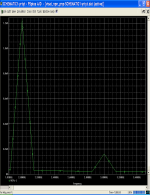
Your FFT is only from 2khz-3.4khz, very narrow. What is the FFT for wider band?
Is the idea of "Differential Replacement" Q1-Q2 really works as a "non-harmonic cancelation" input stage?
Is this better than singleton input like JLH?
Mike,
Nice gift you have. What is the need of C4=10000uF?
Your FFT is only from 2khz-3.4khz, very narrow. What is the FFT for wider band?
Is the idea of "Differential Replacement" Q1-Q2 really works as a "non-harmonic cancelation" input stage?
Is this better than singleton input like JLH?
Mike,
Is that JLH design is trying not-to cancel harmonic?But sadly 2nd harmonic is to easy cancelled out. (With nearly any symetrical circuit, like pushpull)
Is it the fuse that cause it? How come? Whats your design like?Something interesting: in my latest amp (asymetrical, but pushpull) i simulated fuses by adding 0.05ohm to powersupply. And suddenly the amp produced nearly even harmonics only...
Hi, Mike,
Thanks for the explenation. So if the basic tone is 1khz, then 7th harmonic will be 7khz, right?
Is there any cct that can cancel odd harmonics?
Thanks for the explenation. So if the basic tone is 1khz, then 7th harmonic will be 7khz, right?
Is there any cct that can cancel odd harmonics?
Thanh!
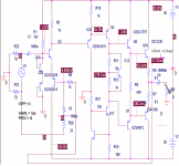
Just observing your gift. Very clever of you, arranging Q1,Q2,Q18,Q23 like that. Dont need servo, but consequence is you have put C5. Is there any possibility not to have C5 / DC coupled in your gift, but still having good DC offset stability?
Is your gift has a "non-harmonic cancelation" properties like my first drawing? Will your wider bandwith FFT similiar to Dad's in post #34?
lumanauw said:Mike,
Is that JLH design is trying not-to cancel harmonic?
Is it the fuse that cause it? How come? Whats your design like?
If i remember JLH right, its very asymetrical, so it shouldn't
cancel out even harmonics. Maybe should simulate ?
The resistance in the fuses (~0.05ohm measured) creates
an asymetrical ripple in the voltagerails. That creates even harmonics.
The design is simple. One diffamp with jfets + bjt-cfp, fed with
ccs, then VAS, and finally "tripledarlington" output, but the
driverstages classA'd. Schooldesign with cfp, optimized
for bandwidth, and very low THD.
With the 0.05ohm at output 16volts into 4ohm, it generates
200uv 2nd, and 15uv 3rd. (1khz)
Without the fuses (or compensated) it makes 30uv 2nd, 10uv 3rd.
Have to try if it sounds different.
I will post some schematics later this evening.
lumanauw said:Hi, Mike,
Thanks for the explenation. So if the basic tone is 1khz, then 7th harmonic will be 7khz, right?
Is there any cct that can cancel odd harmonics?
Yes, if basic tone is 1khz, then 7th harmonic is 7khz.
I am researching if its possible to cancel out odd harmonics,
but the problem is the way harmonics are created. Even harmonics
are phase shifted 90deg, so automatically canceled out by adding
reversed signals in a symetrical circuit. If you can phaseshift the
signal by 90deg before amplifying, you might be able to cancel
odd harmonics. At the moment it seems to be better to keep
odd harmonics low with CFPs or something else.
Hmm,
I just had a thought...
Is it possible, that the distortions generated by the amp are
not really important, but if it generates enough even harmonics,
it masks out the odd harmonics generated by the speaker ?
Mike
I just had a thought...
Is it possible, that the distortions generated by the amp are
not really important, but if it generates enough even harmonics,
it masks out the odd harmonics generated by the speaker ?
Mike
Hi, Mike,
Aah, now I see the difference between single current path input stage (like Dad's FFT #34) and differential input stage (asymamp1_fft2.gif). In single current path, all harmonics, even and odd, are following the same pattern, decaying in the same pattern.
In differential input stage, the odd and even harmonics has their own decay pattern, so it look like mountains. So, this is what differential pair do to harmonics.
Mike, the low odd harmonics in your cct is caused by CFP differential input, isnt it?
I really like the sound of my single current path input stage prototype. The sound has more "Vibration+depth". Dont know what cause this, hope it is the "non-harmonic cancelation" like Dad's #34.
In the spirit of simplicity, thats what we can do without complex cct.....wait a minute..... you say speakers? I tought this is in amplifier.Hmm,
I just had a thought...
Is it possible, that the distortions generated by the amp are
not really important, but if it generates enough even harmonics,
it masks out the odd harmonics generated by the speaker ?
Aah, now I see the difference between single current path input stage (like Dad's FFT #34) and differential input stage (asymamp1_fft2.gif). In single current path, all harmonics, even and odd, are following the same pattern, decaying in the same pattern.
In differential input stage, the odd and even harmonics has their own decay pattern, so it look like mountains. So, this is what differential pair do to harmonics.
Mike, the low odd harmonics in your cct is caused by CFP differential input, isnt it?
I really like the sound of my single current path input stage prototype. The sound has more "Vibration+depth". Dont know what cause this, hope it is the "non-harmonic cancelation" like Dad's #34.
lumanauw said:
Mike, the low odd harmonics in your cct is caused by CFP differential input, isnt it?
I really like the sound of my single current path input stage prototype. The sound has more "Vibration+depth". Dont know what cause this, hope it is the "non-harmonic cancelation" like Dad's #34.
The low odd harmonics are achieved by two things:
1, yes, the CFP. Its not only good for linearizing, it boosts the gain
of the diffamp. Openloopgain of the circuit is ~1:625000.
Its a wonder it doesn't oscillate.
2, the asymetrical design. With symetrical design 2nd and 3rd
harmonic would be exchanged. (like fft1, but exchanged)
The even harmonics in fft2 are generated by the "weak" supply.
I had no time yet to check if it sounds different if i remove this
"weakness".
The amp sounds really good, it has unbelievable clarity and details,
but does not sound soft neither hard. I think it's simply very
accurate. Due to the high gain and bandwidth, high frequencies
are still low distortion.
Its an unbelievable difference to my Yamaha-amp, the Yamaha
is completely outperformed in ANY discipline. (maybe except the
outputpower, the yamaha is rated 110watt, mine is 55watt into 4 ohm)
Mike
Oh! about 800MhzWhat is the FFT for wider band?
🙂 I see that this thread is paying attendtion for 2nd and 3rd so I post the picture which only has 2nd and 3rd
Oh! Do you try? I have not yetIs there any possibility not to have C5 / DC coupled in your gift, but still having good DC offset stability?
😀
Does the word "mask" synonym the word "hide"?MikeB said:Hmm,
I just had a thought...
Is it possible, that the distortions generated by the amp are
not really important, but if it generates enough even harmonics,
it masks out the odd harmonics generated by the speaker ?
Mike
If it right, I think you known about it at least at the first post
I wanted to see the harmonic pattern. Is it smooth like #34 or have mountains like Mike'sI see that this thread is paying attendtion for 2nd and 3rd so I post the picture which only has 2nd and 3rd
You called -12mV quite high? How many amps have you built? You must appreciate -12mV😀 --- I just afraid that prototype doesn't as beautiful as SIM.Because offset voltage is quite high,I think
Thats right, CFP differential is good. What makes it not popular among designers? Just adding 2 small transistor and 2 resistor wont cost much, I think. Or there is "minimalist" principle that wont receive even a component addition?1, yes, the CFP. Its not only good for linearizing, it boosts the gain of the diffamp. Openloopgain of the circuit is ~1:625000. Its a wonder it doesn't oscillate.
- Status
- Not open for further replies.
- Home
- Amplifiers
- Solid State
- Will this work as audio amplifier?