Using a circlomos topology, it's just possible.
The quiescent current is greater than 10mA, about 15mA, but speed and low power are somewhat antinomic.
With some tweaks and more suitable transistors, the target could be reached.
Increasing the complexity is another option.
The quiescent current is greater than 10mA, about 15mA, but speed and low power are somewhat antinomic.
With some tweaks and more suitable transistors, the target could be reached.
Increasing the complexity is another option.
Attachments
Hi friends,
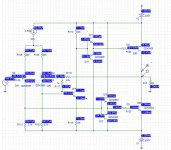
I spiced a complementary symmetry amp with quiescent very much less than 10mA for a almost 380Vpp output. Gain = 34, test = 500kHz, output 200mA rms.
Does it seem like working technique? I am not using power transistor model. (I dont have any)
Can I get better performance if I modify this circuit?
I spiced a complementary symmetry amp with quiescent very much less than 10mA for a almost 380Vpp output. Gain = 34, test = 500kHz, output 200mA rms.
Does it seem like working technique? I am not using power transistor model. (I dont have any)
Can I get better performance if I modify this circuit?
Attachments
Last edited:
I'm trying to help, but I'm afraid it is nearly impossible if you don't provide any further infos. Why is the 10 mA quiescent current so important? And is this the quiescent current for the whole amplifier, or just the output stage? Does the output need to be short-circuit proof? What's the exact impedance of the load (it is not just a pure resistance, I presume)?
Samuel
Samuel
A tease? Me? The circuits are fine, it's the load I'm concerned about. If this is a piezoelectric device, expect the load to be mostly a capacitor, with an unusually high loss factor. A halfway decent simulation load will look a lot like the model for a quartz crystal, but with wildly different values. Without more knowledge of what the device is, and whether it operates at or near mechanical resonance, there's no way to guess at how well a drive circuit will function.
Using a circlomos topology, it's just possible.
Thanks, Elvee, I m reading your thread on CIRCLOMOS
")
I need response from DC to 1MHz (large signal). So I think the cirlclomos w/o modification would be ok.
And honestly, I dont very much understand the topology.
and I think I ve lots to learn.
Last edited:
And is this the quiescent current for the whole amplifier, or just the output stage?
The whole amplifier, but will compromise upto 25mA.
Does the output need to be short-circuit proof?
No.
What's the exact impedance of the load (it is not just a pure resistance, I presume)?
For the time being the load is 1k resistive.
Yes, what is the highest frequency you will pass.
It would give more accurate test in sim.
CFA, I think in this case, will give the hig frequncy operation you want.
I think both VAS and Output could be IRF610/9610.
It is possble to put several 5W resistors in series.
And to increase the value of this resistor a bit.
Say 1k08 total feedback divided by 22 Ohm.
3x5W: 360-360-360/22 (gain 1080/22 +1=50)
4x5W: 270-270-270-270/22
Spice models for 2SA1773/2SC4616 or 2SA1830/2SC4734.........?
Lineup, I would like to build three amplifiers VFB, CFB and the circlomos thing.
1MHz, but dont mind a wider response...what is the highest frequency you will pass.
Lineup, I would like to build three amplifiers VFB, CFB and the circlomos thing.
Last edited:
Very interesting. Once was looking at something like that (a piezo positioning device). Could you please elaborate more or provide some Bibliography/link/documentation on the topic? Especially the part regarding the inductor use.If the transducer is a piezoelectric element, expect it to be a pure capacitor (low impedance current sucker) except near resonance, where it will display the usual resonant circuit peak/dip impedance curve. Potentially a tough load for conventional amplifier designs. Most people use an inductor and operate them as resonant tanks, or some variation thereof.
Thanks in advance
@Audio
I have a new attempt with CFA. With IRF610/9610 output.
With feedback 1080/22 Ohm.
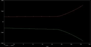
The thing with feedback resistors in CFA is they determine how fast it is.
Lower resistors = faster.
Well, with 1080/22 I get -3db at ~4 MHz
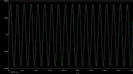
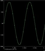
The squarewave in 100kHz looks just fine.
The squarewave in 1 MHz looks bit rounded.
With IRF610/9610 we can only get like 90 Vpeak out.
I attach 1MHz squarewave with 50 Vpeak out. (100 Vp-p, +/-50V)
With feedback 1080/22 Ohm.
The thing with feedback resistors in CFA is they determine how fast it is.
Lower resistors = faster.
Well, with 1080/22 I get -3db at ~4 MHz
The squarewave in 100kHz looks just fine.
The squarewave in 1 MHz looks bit rounded.
With IRF610/9610 we can only get like 90 Vpeak out.
I attach 1MHz squarewave with 50 Vpeak out. (100 Vp-p, +/-50V)
Attachments
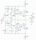
I've sketched an amplifier which should be a good starting point: 1MHz_200Vpp_amplifier.pdf
As the available specifications are sparse, this reflects just my personal interpretation of the task. Output stage bias details and decoupling are omitted, and in no case should this schematic be taken as fully tested design. The involved supply voltages are not to be applied without greatest care.
The transistors which see large collector voltage (Q3, Q6, Q7, Q8, Q11, Q14, Q17 and Q18) should be something like 2SC3503/2SA1381. The remaining bipolars can be ordinary small-signal parts such as 2N4401/2N4403. I didn't look up a specific MOSFET pair; choose the one with lowest capacitances at sufficient power. Something like 1 A/10 W parts.
For a perfectly clean ±100 V output I'd suggest ±120 V rails, although somewhat lower should work as well. Simulation indicates that the amplifier easily reaches the required full power bandwidth. Distortion is below the specifications, although layout effects (in particular inductive crosstalk from the power supplies) will be though to control at these frequencies.
Samuel
I attach 1 MHz squarewave with 50 Vpeak out.
Getting a nice square-wave response is not difficult. Getting distortion at 1 MHz low enough is the main problem...
Samuel
newvirusSpice models for 2SA1773/2SC4616 or 2SA1830/2SC4734.........?
1MHz, but dont mind a wider response...
Lineup, I would like to build three amplifiers VFB, CFB and the circlomos thing.
You are crazy. 3 amplifiers!
Begin with one. Pick one to build.
I have only 2SA1837/2SC4793 spice models. TO-220.
And KSA1381/KSC3503. TO-126
Have you searched with google?
MJE340/350 are 300 Volt video transistors. Maybe for VAS.
Here is a guy with all Orcad library online
power.teipat.gr - /download/OrCad/OrCad Libraries/Library for Capture/PSPICE/
Last edited:
Your amplifier looks good.Getting a nice square-wave response is not difficult. Getting distortion at 1 MHz low enough is the main problem...
Samuel
Now the big question is: What transistors do we use?
Now the big question is: What transistors do we use?
As noted:
The transistors which see large collector voltage (Q3, Q6, Q7, Q8, Q11, Q14, Q17 and Q18) should be something like 2SC3503/2SA1381. The remaining bipolars can be ordinary small-signal parts such as 2N4401/2N4403. I didn't look up a specific MOSFET pair; choose the one with lowest capacitances at sufficient power. Something like 1 A/10 W parts.
There are countless suitable MOSFETs, and the choice will be influence by what's available in India, which I don't know.
Samuel
Hi friends,
My requirements have been relaxed. Now its 500kHz / 400Vpp / gain of 30 only.
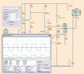
I spiced a CFA with complementary output, 500kHz attached, 1MHz is fine. Idle current <7mA. Please read 2SC3601 / 2SA1407 in place of 2n3904 / 2n3906.
My requirements have been relaxed. Now its 500kHz / 400Vpp / gain of 30 only.
I spiced a CFA with complementary output, 500kHz attached, 1MHz is fine. Idle current <7mA. Please read 2SC3601 / 2SA1407 in place of 2n3904 / 2n3906.
Attachments
I would like to go 400VppwWith IRF610/9610 we can only get like 90 Vpeak out.
what about IRFR320 & IRF9310 ? spice models with vishay.com
I like the N-only circlomos but not able to adapt to +/- 200V supplies.Full power 1MHz bandwidth is unreachable with such a topology.
Last edited:
OK got it. but I dont want to use a ground inside the amplifier. Good PCB can be made if there is only one ground (i.e. near input & f/b network)
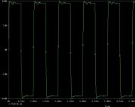
Also want amp to work at lower rails. so current source in the beginning. It will set all quiscent voltages right.
Pls see Iq versus temp graph.
compensation caps were 50pF (1/10th) for sq wave of 1MHz.
But there is no IRF9710
Also want amp to work at lower rails. so current source in the beginning. It will set all quiscent voltages right.
Pls see Iq versus temp graph.
compensation caps were 50pF (1/10th) for sq wave of 1MHz.
N-Channel IRF710, IRF7xx are 400V devices.
But there is no IRF9710
Attachments
Last edited:
- Status
- This old topic is closed. If you want to reopen this topic, contact a moderator using the "Report Post" button.
- Home
- Amplifiers
- Solid State
- Wide bandwidth class AB with 10mA quiescent?