Thx. I'm just an old goat not so willing to go back into the classroom.....when I can be out experimenting in the lab.😀I know. And I was trying to show you that it could be done, thereby encouraging you to do it yourself. It's a carryover from the old comp.dsp days, where there was an unwritten rule that we would help students with their homework, but not do their homework for them.
Actually, negative frequency is very real. It becomes obvious when signals are amplitude-modulated. In fact, if you perform a thought experiment in which an unmodulated signal is actually amplitude-modulated by DC, the math suddenly makes sense.And, yes, there's negative frequency in signal processing, and it exists for mathematical convenience.
That will produce the square of the filter response, not the filter response.
Yes, but they would be of same length after the convolution, one each of minimum and linear phase, comparable to each other.
I know. And I was trying to show you that it could be done, thereby encouraging you to do it yourself. It's a carryover from the old comp.dsp days, where there was an unwritten rule that we would help students with their homework, but not do their homework for them.
I get that Sir, but I don't think the people here are always technically/mathematically inclined, that's the issue.
Last edited:
I posted two Linear phase ones by mistake, later updated the files. Check now. Also, when two signals of length N are convoluted with each other, the resulting length is 2N-1, which in this case is 2*4096 - 1 = 8191. Hope you know that. You may zero pad to the nearest (8192).I'm measuring that both your versions show a FIR time delay of 85.29ms, which is about 2 samples short of the entire 4096 taps@48kHz filter length.
Last edited:
I did a little experimentation with exactly that question. It turns out that the impulse responses are very similar, until far out on the tails. I've attached a representative example (happens to be 200 Hz crossover frequency, only because that plotted nicely). If one assumes, for example, that the FIR filter will be truncated where the coefficient magnitudes drop below 2^(-24) [5.96e-8], then the slight advantage of the Gaussian-derived filter becomes apparent. Is it worth the effort? Hard to say.... if implemented using FIR what is the advantage compared to a pair of 4th order [linear-phase] LR filters, which will also sum with no ringing.
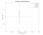
EDIT; sorry, "G4 high" and "G4 low" labels are swapped. I was in a hurry.
Attachments
Nope, I didn't know that.I posted two Linear phase ones by mistake, later updated the files. Check now. Also, when two signals of length N are convoluted with each other, the resulting length is 2N-1, which in this case is 2*4096 - 1 = 8191. Hope you know that. You may zero pad to the nearest (8192).
Doesn't doubling taps undo the entire point of my test/questioning ?
Sure, that will double up freq resolution to equal that of the original min phase version......and a transfer function of your new files now shows equal magnitude between your versions
But all along i've been talking about comparative frequency resolution for the same size file. .....impulse at start vs center
A 4096 tap lin phase version is what's needed for a valid test, isn't it?
Oh, by my measurements, the new files are still amiss.....they're somehow magnifying the filters in my original file.
The EQ at 100Hz is only +5dB....here's a transfer of the your new min-phase version showing about +10.

And here's one, my min phase as reference, yours as measurement

and thx again for these!
Mark,
Here's the code I used (if it helps)
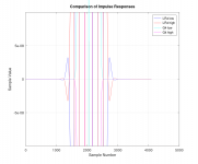
And the plots that resulted are also attached below. The shift in impulse peak clearly shows how both these have the same magnitude response but with different phase characteristics. The takeaway here is that no filter is fully defined unless both its magnitude and phase characteristics are specified.
- I gave you two files with equal magnitude responses, one minimum phase and one linear, which you did not believe was possible.
- Do not compare the files I sent with the original, as the ones I've given have the squared response of your original (as result of the convolution).
Here's the code I used (if it helps)
Code:
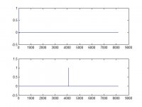
[x,Fs,N] = wavread('Test.wav');           % Original wave file, 4096 pts
[y,Fs,N] = wavread('RevTest.wav');      % Reversed wave file, 4096 pts

MinPhase = conv(x,x);                        % Squares the response
wavwrite(MinPhase,Fs,N,'h:\desktop\mark100\MinPhase.wav');        % Writes wave file

LinPhase = conv(x,y);                          % Squares the response with linear phase
wavwrite(LinPhase,Fs,N,'h:\desktop\mark100\LinPhase.wav');           % Writes wave file

subplot(2, 1, 1), plot(MinPhase);
subplot(2, 1, 2), plot(LinPhase);
And the plots that resulted are also attached below. The shift in impulse peak clearly shows how both these have the same magnitude response but with different phase characteristics. The takeaway here is that no filter is fully defined unless both its magnitude and phase characteristics are specified.
Attachments
Last edited:
I think we're just approaching this from two different points of view. 🙂Mark,
- I gave you two files with equal magnitude responses, one minimum phase and one linear, which you did not believe was possible.
- Do not compare the files I sent with the original, as the ones I've given have the squared response of your original (as result of the convolution).
I never said I didn't believe it is possible to have equal magnitude responses, with one minimum phase and one linear phase filter.
I'll quote myself from #152
How can you get exactly the same magnitude response like that..... where the two files have the same number of taps and sample rate?
I can see how it could be done with an enormous FIR file, one that had so many taps that the frequency resolution in linear phase mode is sufficient to get close to frequency resolution in minimum-phase mode.
But that's seldom the real world case. With typical FIR filter sizes/sample rates, i think it would be very rare to be able to make both min-phase and lin-phase filters have the same magnitude response / frequency resolution. Maybe for VHF work only?
I bolded two parts.... first, 'But that's seldom the real world case'.
Outside of computer FIR, you rarely see hardware capability reach past 8k taps per channel
The original file i posted i consider a real world case, only 4k taps to work with.
(i used only two simple filters as i thought they were enough for the case)
Second bolded part....'one that had so many taps that the frequency resolution in linear phase mode is sufficient to get close to frequency resolution in minimum-phase mode'
That's what i think you achieved by effectively doubling the frequency resolution of the linear phase file you made. It then equals the resolution needed to match the original.
The original really didn't really need any increase in resolution for the simple file it was asked to produce, and its minimum phase resolution is effectively unaltered by a tap doubling doubling. Transfers i've run show this.
So the tab doubling really only serves to provide enough taps, such that my example goes to equivalent magnitude.
So, all i still want is a 4k taps FIR wav used lin-phase, that replicate the original min-phase magnitude. I dunno how. (and yes, still wonder if it can be done)
Oh, How do you get rid of the effect on magnitude from squaring the response? Shouldn't your new files at least have the same magnitude as the original? (i won't go back again to same 4k file size again ...but yes i did ...lol)
You know, if all this had just started with a 65k FIR file size....there certainly wouldn't be any realistic question about freq rez, huh?1
Look closely at the graphics in post #161. Yes, it can be done. An no, I'm not going to do it for you.So, all i still want is a 4k taps FIR wav used lin-phase, that replicate the original min-phase magnitude. I dunno how. (and yes, still wonder if it can be done)
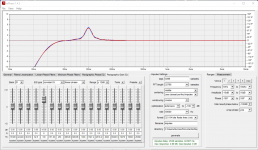
In RePhase, if you set optimization to moderate, it will make the magnitude the same, while slightly letting go of the (minimum) phase shape:
(while keeping the impulse centered with 4096 taps)

But that's beside the point Mark is trying to make. 😉
(while keeping the impulse centered with 4096 taps)
But that's beside the point Mark is trying to make. 😉
Last edited:
Yes, I'm simply demonstrating something (for free), but you're expecting something else.I think we're just approaching this from two different points of view. 🙂
Then, why didn't you provide an impulse response of "typical" size in the first place, why 4096 points ?With typical FIR filter sizes/sample rates, i think it would be very rare to be able to make both min-phase and lin-phase filters have the same magnitude response / frequency resolution.
I don't know what to say to this.Second bolded part....'one that had so many taps that the frequency resolution in linear phase mode is sufficient to get close to frequency resolution in minimum-phase mode'
That's what i think you achieved by effectively doubling the frequency resolution of the linear phase file you made. It then equals the resolution needed to match the original.
The original really didn't really need any increase in resolution for the simple file it was asked to produce, and its minimum phase resolution is effectively unaltered by a tap doubling doubling. Transfers i've run show this.
So the tab doubling really only serves to provide enough taps, such that my example goes to equivalent magnitude.
What I gave was only a demonstration, based on what Mr. Berchin suggested in post #153, since you were expecting an output file that could be sent across the internet and tried out.So, all i still want is a 4k taps FIR wav used lin-phase, that replicate the original min-phase magnitude. I dunno how. (and yes, still wonder if it can be done)
Oh, How do you get rid of the effect on magnitude from squaring the response? Shouldn't your new files at least have the same magnitude as the original?
Here, try this.So, all i still want is a 4k taps FIR wav used lin-phase, that replicate the original min-phase magnitude. I dunno how. (and yes, still wonder if it can be done)
Oh, How do you get rid of the effect on magnitude from squaring the response? Shouldn't your new files at least have the same magnitude as the original? (i won't go back again to same 4k file size again ...but yes i did ...lol)
Attachments

Yes it is about making sure that the processing doesn't add extra latency. I have found a paper that references using partitioned convolution with non LTI impulses, maybe it is wishful thinking to hope something like that might be able to work in a broader sense. There has to be some look ahead function but does it have to be until the impulse peak?Pls correct if needed,.... the explanation of different types of convolutions link, appeared to be about minimizing CPU processing latency, with little to do about minimizing 'FIR time latency'.
https://ntnuopen.ntnu.no/ntnu-xmlui..._9_innsendt_Sigurd.pdf?sequence=1&isAllowed=y
Going back to reversing an IIR filter I came across something interesting a while ago and in this they give an example of 64 samples of delay with an LR4 at 1K which seems like it might scale to still be quite low at 100Hz.
https://www.vicanek.de/articles/ReverseIIR.pdf
I don't understand the equations or how it could be realised but perhaps someone else does 🙂
The method cited above avoids block processing to reduce the time-reversal latency, by adopting a different IIR filter structure altogether. However, it also requires a filter implementation (programming) that is different from the classical one.
The block-based methods, on the other hand, still used the conventional IIR filter structures (in the original manner), with manipulations only in the order/sequence of the input/output samples.
The block-based methods, on the other hand, still used the conventional IIR filter structures (in the original manner), with manipulations only in the order/sequence of the input/output samples.
Thx newvirus, and all, for your continued contributionsHere, try this.
Yes, that 4k file with impulse centering looks good in comparison to the 4k file i posted with impulse at start.
And I see what gberchin posted, which also looked fine, had the right sample counts.
As did the more optimized rePhase version wesayso posted.
So it's clear optimization can help overcome low taps counts, that have marginal frequency resolution for a desired filter set.
For the case I posed.... 4k taps@48kHz, with two simple filters, we have success !!
Magnitude response, impulse start vs center, that's close to identical.
Now, anybody think that success will be achievable if we cut taps in half, (or hold tap count and raise the sampling rate)?
Or move the PEQ from 100Hz to 50Hz, or raise the PEQ's Q from 6 to say 10? Or increase the order of the high-pass? Or add more PEQ's, both boosts and cuts?
Point being the test wasn't that hard, and I think optimization can only go so far.
In the end isn't it just a matter of having sufficient taps for the desired filter set. Wheter the filter set be for minimum, linear, or mixed phase?
So with great trepidation 🙂..... I'd like to amend my theory on how taps work pragmatically:
The amount of FIR time (#taps@sample rate) after the impulse peak is the primary factor in determining frequency resolution,
and the amount of FIR time before the impulse peak is the primary factor in determining time resolution.
Do folks think that assessment holds water?
Thx fluid, yep way above my head too.Yes it is about making sure that the processing doesn't add extra latency. I have found a paper that references using partitioned convolution with non LTI impulses, maybe it is wishful thinking to hope something like that might be able to work in a broader sense. There has to be some look ahead function but does it have to be until the impulse peak?
https://ntnuopen.ntnu.no/ntnu-xmlui..._9_innsendt_Sigurd.pdf?sequence=1&isAllowed=y
Going back to reversing an IIR filter I came across something interesting a while ago and in this they give an example of 64 samples of delay with an LR4 at 1K which seems like it might scale to still be quite low at 100Hz.
https://www.vicanek.de/articles/ReverseIIR.pdf
I don't understand the equations or how it could be realised but perhaps someone else does 🙂
Heck, i was a math minor in undergrad....got as far as a couple of courses in diff equations, really enjoyed linear algebra. It's all Greek now 🙁😛
I can't help but believe, the idea it takes time to correct time, holds true no matter the mousetrap. But lord knows, you guys have pruned a number of my intuitive beliefs. And I sincerely thank all of you !
Partitioned convolution only helps to minimize the time required to process the FIR impulse via DFT, etc. It cannot do anything about the delay that is built into the kernel itself, the one that is required for it to be causal and stable.
Every sample within the impulse response no matter where it is located still contributes to time / frequency resolution. And, there's no alternative to formal education.The amount of FIR time (#taps@sample rate) after the impulse peak is the primary factor in determining frequency resolution,
and the amount of FIR time before the impulse peak is the primary factor in determining time resolution.
Do folks think that assessment holds water?
And complex number theory ?Heck, i was a math minor in undergrad....got as far as a couple of courses in diff equations, really enjoyed linear algebra.
- Home
- Loudspeakers
- Multi-Way
- Why not IIR filters + a global phase linearization by FIR