Will give it a go 🙂
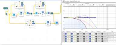
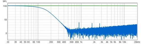
I have never used the parametric EQ block like that and don't therefore know whether it will work the way you expect. What happens if you display a larger level range like between -80 and +10 dB ? Does the resulting filter really look like a lowpass ? And what happens if you use 2nd order filter blocks ?
Regards
Charles
Regards
Charles
hmmm, will check the second order blocks later.I have never used the parametric EQ block like that and don't therefore know whether it will work the way you expect. What happens if you display a larger level range like between -80 and +10 dB ? Does the resulting filter really look like a lowpass ? And what happens if you use 2nd order filter blocks ?
Regards
Charles
Attachments
Forgive me; I'm only paying about 10% attention to this while I do other things.Something still not working this end, will take another look this evening 🙁
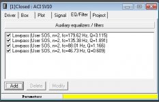
The -6dB frequency of the Bessel LPF has to be adjusted further. Realize that, if the -6dB frequency of the first HPF is 100Hz, and the output of that is passed through another 100Hz HPF, then the new -6dB frequency will become something greater than 100Hz. So we have to account for that by adjusting the HPF -6dB frequency downward. Specifically:
"adjusted -6dB frequency" = "desired -6dB frequency" / 1.292 (This only works for 8th-order Bessel. Other orders require different adjustments.)
This means that, in order to achieve a final crossover frequency of 100Hz, you have to design the 8th-order Bessel filters for 77.4Hz by frequency-scaling as I indicated in my earlier message.

I have never used the parametric EQ block like that and don't therefore know whether it will work the way you expect. What happens if you display a larger level range like between -80 and +10 dB ? Does the resulting filter really look like a lowpass ? And what happens if you use 2nd order filter blocks ?
Regards
Charles
Attachments


Just could do with getting a GB_B4x4 working as I think for live sound applications it would be the most useful of them all, manageable amount of delay, lower delay than any FIR that comes even close to the performance, filters steep enough and a solid replacement for the industry standard LR24.
Also free of ringing when not 100% summed in the acoustic domain unlike the LR filters.
I think it is very much you that deserves the congratulations 🙂
Also free of ringing when not 100% summed in the acoustic domain unlike the LR filters.
I think it is very much you that deserves the congratulations 🙂
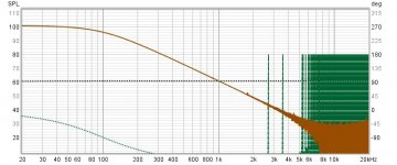
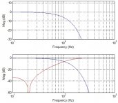
Here's another filter for the IIR-oriented people (8th order) that combines the group delay flatness of the Bessel with the roll-off of Butterworth. The group delay is essentially flat upto 180Hz (far beyond the cutoff frequency), where the magnitude response has already fallen below -24dB.
I doubt whether the amplitude response shown is actually that of a higher order Butterworth lowpass. But the idea of using group-delay EQ on the lowpass or using filter types with constant GD abvove cutoff is very good. Maybe a fourth-order Bessel LP with some allpass GD EQ does it also. Keep in mind that even very high order Bessel filters don't have a very steep initial rolloff.
I find gberchin's idea of cascading derived highpass filters very elegant.
I did also experiment with subtractive delay crossovers but I always cascaded crossovers instead of derived highpass filters directly, when going for steeper high pass branches. This did also work but it definitely looks less elegant. It does have a small advantage however: A little bit of memory space for the signal delay can be saved by cascading crossovers.
Regards
Charles
The filter is midway between Bessel and Butterworth, known as the Butterworth-Thompson type. The biquad details are attached for anyone who'd like to see their characteristics in detail, in person.I doubt whether the amplitude response shown is actually that of a higher order Butterworth lowpass.....Keep in mind that even very high order Bessel filters don't have a very steep initial rolloff.
Theoretically, yes, but if I'm not wrong, that's going to take more effort. However, for the 4th Butterworth-Thompson, the delay extension reaches only to -8dB point (vs.-24dB above), suggesting how non-scalable such characteristics can be.Maybe a fourth-order Bessel LP with some allpass GD EQ does it also.
Is you Gaussian version, by any chance, supposed to look like the one below ? Is the delay meant to increase the roll-off rate around the transition region of the high-pass?I generate the Gaussian lowpass impulse response from the mathematical definition. I don't remember off the top of my head the equation to calculate the time-domain variance that leads to the desired -6 dB point in the frequency response, but it is straightforward from the mathematical definition. Or you can simply try values until you get the response that you desire.
Attachments
Last edited:
In the paper that I attached to message #105 I describe an implementation shortcut that eliminates one delay buffer.I did also experiment with subtractive delay crossovers but I always cascaded crossovers instead of derived highpass filters directly, when going for steeper high pass branches. This did also work but it definitely looks less elegant. It does have a small advantage however: A little bit of memory space for the signal delay can be saved by cascading crossovers.
No, the Gaussian version uses a true mathematical Gaussian "Bell Curve" in the time domain:Is you Gaussian version, by any chance, supposed to look like the one below ? Is the delay meant to increase the roll-off rate around the transition region of the high-pass?
x(t) = [1/(sqrt(2·pi·sigma)]exp[-t²/(2·sigma²)]
This is truncated on both ends when the amplitude falls below some suitably low threshold. The delay in the time domain is only to make the zero-phase Gaussian waveform causal.
The time-domain Gaussian produces another Gaussian in the frequency domain:
X(f) = exp[-½(2·pi·sigma·f)²]
You can rearrange the X(f) equation to solve for the value of sigma that produces X(f) = ½ at the desired value of f, then substitute that into the x(t) equation to create the time-domain impulse response and FIR filter coefficients.
True, in comparison to most other filters. But the lowpass and highpass sum perfectly, and the slow rolloff is the reason that the impulse response has nearly zero overshoot and ringing. As always, the crossover frequency and topology selections must be made with the characteristics of the loudspeaker drivers in mind.Keep in mind that even very high order Bessel filters don't have a very steep initial rolloff.
Maybe I was a little unclear. I wanted to say that there is probably not so much to be gained using an 8th order Bessel over using a fourth order one from the rolloff point of view.
Regards
Charles
Regards
Charles
- Home
- Loudspeakers
- Multi-Way
- Why not IIR filters + a global phase linearization by FIR