

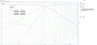
For better results I recommend at least 4th-order, preferably 6th or 8th, or even 10th. (All increase delay, however.)Here's a second order derived Bessel subtractive crossover at 100Hz as per Greg Berchin. 2.77ms delay.
EDIT: BTW, there is nothing to prevent an odd-order Bessel-derived crossover. But if you're going to implement a biquad anyway, you might as well use both halves of it.
For better results I recommend at least 4th-order, preferably 6th or 8th, or even 10th. (All increase delay, however.)
EDIT: BTW, there is nothing to prevent an odd-order Bessel-derived crossover. But if you're going to implement a biquad anyway, you might as well use both halves of it.
Attachments
SubSonics, how are you liking OSM ?
I think a donate-ware, real-time mag & phase dual channel FFT, could be a huge benefit to multi-way DIY.
I think a donate-ware, real-time mag & phase dual channel FFT, could be a huge benefit to multi-way DIY.
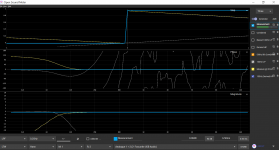
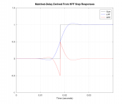
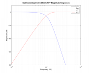
I also tried mr. Berchin subtractive cascaded filter approach for both sections connected in phase and out of phase and compared it to the classical subtractive delay filter approach using double length single delay line. As the theory predicts, frequency response of the classical and Mr. Berchins "out of phase" filter completely match and exhibit approximately 12dB/oct rolloff, whereas "in phase" connection demonstrates ~24dB/oct rolloff and have higher frequency response ripple in the passband. It seems that Mr. Berchin's approach does give a steep filter rolloff, but requires a deeper theoretical insight to minimize ripples in the passbandHere's a second order derived Bessel subtractive crossover at 100Hz as per Greg Berchin. 2.77ms delay.
Attachments
I don't know where this "in phase" connection idea came from, but I have never advocated it.I also tried mr. Berchin subtractive cascaded filter approach for both sections connected in phase and out of phase
If there are ripples in the lowpass passband, then your filter is designed incorrectly. If there are ripples in the highpass passband, then the order of the lowpass filter is too low, or your delay is not quite correct, or both.It seems that Mr. Berchin's approach does give a steep filter rolloff, but requires a deeper theoretical insight to minimize ripples in the passband
I don't know where this "in phase" connection idea came from, but I have never advocated it.
If you compare expression from your pdf document for impulse response ht4
ht4= x(t-2d) - 2x(t-d)*g + x(t)*g*g
("*" means convolution)
and expression for transfer function Hhp2(s) from this my post
Hhp2(s) = exp(-(2*tau)*s) - 2*Hlp*exp(-tau*s) + Hlp(s)*Hlp(s)
("*" means multiplication)
you actually see that it is the same equation but in the frequency domain. I explained in the detail in the my post why I call this "in phase" connection.
Oh, i'm sorry, I just now noticed that in that my post I mistakenly wrote
So, if stages 1 and 2 are connected in phase we get 4th order LP crossover.
I have to correct the statement
So, if stages 1 and 2 are connected in phase we get 4th order HP crossover.
If there are ripples in the lowpass passband, then your filter is designed incorrectly. If there are ripples in the highpass passband, then the order of the lowpass filter is too low, or your delay is not quite correct, or both.
I used Linearx filtershop built-in "2nd order Gauss filter" (from analog Allpole filter design window) to generate analog Gauss filter frequency response and then I used invariant impulse approximation method to generate digital IIR. It seems that Filtershop uses some approximation to generate analog Gauss filter frequency response (I used different delay values, however, the ripples still exist).
I apologize; I misunderstood. I thought that someone, somewhere, had tried adding the delayed full-bandwidth signal to the filter outputs, instead of subtracting it, which is contrary to the perfect-reconstruction objective of the topology.I explained in the detail in the my post why I call this "in phase" connection.
There are two forms of the Gaussian-derived matched-delay-subtractive crossover. The first (original) form uses a single Gaussian (or Bessel approximation) LPF and subtracts the delayed full-bandwidth signal from its output to create the HPF. The highpass band in this case has 12 dB/octave slope, while the lowpass band has the slope of the LPF. The second (modified) form uses two cascaded Gaussian-derived (or Bessel-derived) matched-delay-subtractive HPFs, and subtracts the delayed full-bandwidth signal from their output to create the LPF. The highpass band in this case has 24 dB/octave slope, while the lowpass band has slightly less slope than the LPFs used to create the cascaded HPFs.
Unfortunately, it is easy to get a bit undisciplined with the language. Referring to either of these crossover networks as "in phase" or "out of phase" simply leads to confusion. In all cases, the full-bandwidth signal is subtracted from the filtered signal.
In both forms, if a true Gaussian pulse is used as the LPF(s), and the delay is correctly dialed-in, there will be no ripple in either passband. If Bessel LPF(s) are used, there may be slight ripple in the HPF passband that depends upon the LPF filter order used and the accuracy of the delay time. In fact, there are cases where the optimum delay does not correspond exactly to the peak in the Bessel LPF impulse response. While one could solve for the optimum delay analytically, it is far easier to do it experimentally.
Then the observed ripple is the fault of the LinearX approximation, not of the matched-delay-subtractive topology. I generate the Gaussian lowpass impulse response from the mathematical definition. I don't remember off the top of my head the equation to calculate the time-domain variance that leads to the desired -6 dB point in the frequency response, but it is straightforward from the mathematical definition. Or you can simply try values until you get the response that you desire.I used Linearx filtershop built-in "2nd order Gauss filter" (from analog Allpole filter design window) to generate analog Gauss filter frequency response and then I used invariant impulse approximation method to generate digital IIR. It seems that Filtershop uses some approximation to generate analog Gauss filter frequency response
I used Linearx filtershop built-in "2nd order Gauss filter" (from analog Allpole filter design window) to generate analog Gauss filter frequency response and then I used invariant impulse approximation method to generate digital IIR. It seems that Filtershop uses some approximation to generate analog Gauss filter frequency response (I used different delay values, however, the ripples still exist).
Please understand that there's no such thing such as an "analog or IIR Gaussian filter". This is because the Gaussian function gets steeper and steeper as one moves higher in frequency, requiring an infinite number of bi-quads to replicate it. I already said this in response to TNT in post #137, but I'll say again so that people need not waste their time trying to achieve the impossible.
Anyone interested in using the Gaussian curve would have to use FIR techniques to replicate it faithfully. If you don't have FIR capability, then use a high-order Bessel filter (max flat delay), with the appropriate frequency offsets, like SubSoniks has done above.
Now, if you're too lazy to do the FIR Gaussian, please see post #218, where you may download the impulse responses of two such filters. You may also change the sample-rate to adjust the cutoff frequency to your liking.
Ok, got it.All the transfers I've posted have constant (propagation) delay removed.
I'm liking it a lot, not got mega bucks to splurge on Smaart or Easera so a bit of a godsend really. They're steadily adding features and fixing bugs, now very much usable, just hoping my request for an 'infinite' mode on the realtime charts is added in addition to the 0.25Hz-1Hz which would be really useful for averaging over the listening area, to work out what is modal and what is a badly setup LF - quick and dirty - I mostly do live sound and on occasion land on some abomination of a system to be sorted out. Can't always take mine 🙁SubSonics, how are you liking OSM ?
I think a donate-ware, real-time mag & phase dual channel FFT, could be a huge benefit to multi-way DIY.
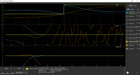
Something is wrong. Here is what I get under the same conditions; 9.0625 ms delay (twice).Greg Berchin Bessel derived 8th order LP / 4th order HP, 13.04ms delay.
Attachments
Last edited:
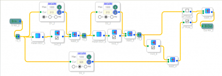
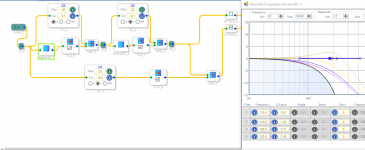
I made a mistake with the higher order Bessel filters, somehow managed to use 'real part' instead of the F0, was a long day, I'm in the process of re doing all of them now. Did you take a look at my schematic for the 4th order HP posted above?Something is wrong. Here is what I get under the same conditions; 9.0625 ms delay (twice).
I did just now. I usually subtract the full-bandwidth signal from the filtered signal, whereas you appear to do the opposite, but that should only affect polarity. Other than that, I didn't see anything obviously wrong.Did you take a look at my schematic for the 4th order HP posted above?
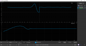
Your Bessel LPF should be -6dB at the crossover frequency, not -3dB.Something not right this end....
I'm using the Analogue Devices filter table, page 8.48:
https://www.analog.com/media/en/training-seminars/design-handbooks/basic-linear-design/chapter8.pdf
https://www.analog.com/media/en/training-seminars/design-handbooks/basic-linear-design/chapter8.pdf
Here are the denominator equations for an 8th-order Bessel LPF that is -6dB at 1.0 radians/second. You will have to frequency-scale them for -6dB at 2pi*100 radians/second, by substituting "s/(2pi*100)" for "s" in the equations and doing some algebra.
(Q = 1.22567) s² + 1.28299239215439s + 2.47283345436118
(Q = 0.71085) s² + 1.9741153642581s + 1.96926212166436
(Q = 0.55961) s² + 2.35216938769735s + 1.73263396575613
(Q = 0.50599) s² + 2.52527503176501s + 1.6326875194579
EDIT: corrected radian frequency
(Q = 1.22567) s² + 1.28299239215439s + 2.47283345436118
(Q = 0.71085) s² + 1.9741153642581s + 1.96926212166436
(Q = 0.55961) s² + 2.35216938769735s + 1.73263396575613
(Q = 0.50599) s² + 2.52527503176501s + 1.6326875194579
EDIT: corrected radian frequency
Last edited:
- Home
- Loudspeakers
- Multi-Way
- Why not IIR filters + a global phase linearization by FIR