10€ for a transistorI think, it is more like FM noise but with added crackling.
That would be cheap. Had I known which transistor is responsible, I would have paid even 100 Euro.10€ for a transistor
Another way is to approach the suspect with a soldering iron's tip.The classic way to find a noisy part is with a can of freeze spray.
Hot of course.
But don't touch the transistors, some of them will melt.
Leave enough cooling time before you do the next one and work carefully since the circuits will be powered.
Very cheap 🙂
Hugo

Cold or once the amp has warmed up?One amplifier channel has much more which noise and some crackling compared with the other channel
I usually don't recommend swapping parts across left / right channels but in this case I wouldn't mind doing so.
Hugo
Hugo
I will not swap parts from the working channel as it is working very satisfactorily. At least, that way, I have a channel that is working to my expectations.
The noise is prevent even as soon as the amplifier is powered up and is cold. There is no need to warm it up. In fact, I never used as much power as to raise the temperature of the power stage. This is a large amplifier: if it produces 10W, it is like being idle. With four pairs, (2SC5200, 2SA1943) it can produce about 400W RMS of power which is far more than enough for my use case. Even 1W has a respectable volume.
The noise is prevent even as soon as the amplifier is powered up and is cold. There is no need to warm it up. In fact, I never used as much power as to raise the temperature of the power stage. This is a large amplifier: if it produces 10W, it is like being idle. With four pairs, (2SC5200, 2SA1943) it can produce about 400W RMS of power which is far more than enough for my use case. Even 1W has a respectable volume.
I understand, but eventually you'll have to do 'something'... 😉I will not swap parts from the working channel as it is working very satisfactorily
Hugo
huggywood said:Have you a variac ?
You can try starving the power supply and see if the phenomenon changes.
This is running already using a low voltage. Instead of 230V AC, I am supplying it with 48V AC, or at most 60V AC. The circuit design allows for a very wide power voltage range. In a home setup using about 80V DC per rail does not make much sense, as the power requirement is very low. A few watts of power produce enough sound intensity for me. Besides that, high volume levels can be annoying to neighbours, and can also be illegal.
A channel works perfectly with the much reduced voltage. Calculation shows that the rails are being supplied 17V peak. Allowing 3V for a massive ripple, leaves 14V DC. Assuming 2V are needed for the output transistors to work properly, leaves 12V peak for the output. This produces a peak power of 12^2/8 = 18W peak. This is far more than enough for the room.
The failing DC offset trim pot will do that. I am not sure if there's a trim pot inside that amp because you posted schematics for LT Spice.
The photos would help...
I tend to feed a 1kHz signal and then start monitoring the signal with an oscilloscope, from the input, one gain stage at a time, progressing towards the output. The good thing about your issue is that you have a perfectly fine working channel, so you could feed the same 1kHz signal to both channels.... and compare.
Reading about electrolytic capacitors I learnt these suffer from various issues, one of them being, current leak. These leaks are also random in nature which agrees with the nature of the crackling. This is random. I also learnt that electrolytics heal themselves. The oxide layer is the dielectric and the electrolyte forms an electrolytic cell in series with the actual capacitor. The motion of ions in the electrolyte is random and produces some random noise. Furthermore, the fact that defects heal themselves and take time to do so, corroborates the conclusion that an electrolytic capacitor may be responsible. A signal can be injected at both the non-inverting and inverting inputs, which means, irregular currents in a slightly leaking capacitor, can affect the amplifier performance. Such a capacitor acts as a voltage signal source that is unwanted and problematic.
I know the electrolytic capacitor I used are not those expensive types advertised 'for audio'. A normal power supply capacitor may leak. In a power supply this is not problematic but in audio it is an unwanted signal source.
I have two canditate components for replacement: the input capacitors and the differential pair transistors.
The random noise can be displayed on an oscilloscope. In fact, I did exactly that when I built the amplifier. The DC offset can be observed to jump randomly. This is possible if the oscilloscope is set to view voltages in the millivolt range. However, it seems to me it is impossible to verify which component is the source of trouble by using an oscilloscope. If some reader knows a way, please, post how. I have an oscilloscope sitting lazily on a shelf which I can use.
Last edited:
I don't think you can locate it with a scope for the crackle will be everywhere.
Really your easiest options are freezing or heating and listening for changes.
Hugo
Really your easiest options are freezing or heating and listening for changes.
Hugo
That is my worry. With feedback, the amplifier works as a whole as there are no stages not affected by the output.Netlist said:I don't think you can locate it with a scope for the crackle will be everywhere.
I will use a low voltage split DC power supply for the rails and use a soldering iron to change the temperature of components.
Good, take your time with the iron. leave plenty of time for cooling
before taking on another component and check off the parts you did on the schematic.
Hugo
before taking on another component and check off the parts you did on the schematic.
Hugo
I have a hot air station with a temperature range of 100C to 500C. I will set the air temperature to 100C and heat the component without making contact. The hot air station has three nozzles to choose from. I will choose the narrowest one and adjust the fan speed accordingly.
The output will be connected to an oscilloscope (USB type) connected to a laptop while operating with the battery. This avoids noise from the switched mode power supply. The noise shows as periodic ringing superposed on the signal.
The output will be connected to an oscilloscope (USB type) connected to a laptop while operating with the battery. This avoids noise from the switched mode power supply. The noise shows as periodic ringing superposed on the signal.
Cold spray seems to have become expensive, so first thing to do is just use a plastic tool to tap the suspect parts. When you hit the culprit, you should hear a big burst of noise. You may hear "microphonics" as you get close to it, and have to be gentle as you home in on the culprit.
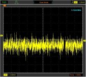
The "random noise" from the defective channel has increased substantially and is characteristic of the noise gerated by a bad connection.
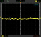
Switching off and then on again resulted in less noise.
Switching off and then on again resulted in less noise.
Last edited:
I am attachment three screenshots from the oscilloscope. Two screenshots show the trace with a time base of 1s and 20s. What is causing these oscillations?
Attachments

Last edited:
- Home
- Amplifiers
- Solid State
- White noise and slight crackles in one amp channel