@ Diyers
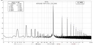
Ok at 1 Watt get nice distortion 2 harmonic profile many amp's can show similar figures
but at 20 or 50 Watts distortion rise super fast and % is much higher with Tokin's.
Again maybe from J Broskie article or from MEPER post # While they last...
Sakuma style solution..or new Mr. Pass ?
Can be interesting to learn and experiment.
Use LTSpice first so no danger of smell the smoke
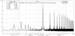
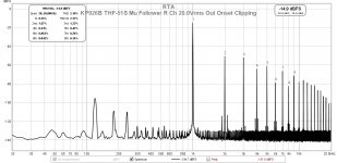
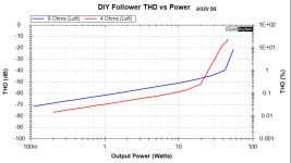
Mu follower common drain THF-51S at onset of clipping (50W into 8 Ohm), left and right channels. Two percent THD is quite good and probably no worse than VFETs, except VFET can't output 50W.
20W added.
20W added.
Attachments
Last edited:
WOW,fantastic.
My plan DN2540 buffer and then KP926 driver 2SK182/THF-51S follower with chock load.I am waiting for the chassis.
Also I am consider ZM's buffer.
My plan DN2540 buffer and then KP926 driver 2SK182/THF-51S follower with chock load.I am waiting for the chassis.
Also I am consider ZM's buffer.
@ Diyers
Ok at 1 Watt get nice distortion 2 harmonic profile many amp's can show similar figures. . .
Use LTSpice first so no danger of smell the smoke
here my experimental set for the source followers
Various feedback, also the famous F6-style feedback.
The transformer is modelled so-so, could be improved
Attachments

Thanks for the experimental set, but there is a problem with loading.
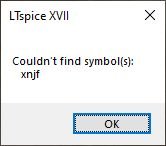
I replaced the missing symbol with an 'njf' and set the prefix to 'X'. Now everything is OK.
here they are
XNJF.asy looks as follows (cant upload the symbol)
Place it with a text editor where the LTSpice can find it. I have it high on the file structure, but it really should be where other ASY's are.
XNJF.asy looks as follows (cant upload the symbol)
Version 4
SymbolType CELL
LINE Normal 16 16 16 80
LINE Normal 48 72 48 96
LINE Normal 16 72 48 72
LINE Normal 48 24 48 0
LINE Normal 16 24 48 24
LINE Normal 0 64 4 64
LINE Normal 4 68 16 64
LINE Normal 4 60 16 64
LINE Normal 4 60 4 68
WINDOW 0 56 32 Left 2
WINDOW 3 56 72 Left 2
SYMATTR Value NJF
SYMATTR Prefix X
SYMATTR Description N-Channel JFET
PIN 48 0 LEFT 5
PINATTR PinName D
PINATTR SpiceOrder 1
PIN 0 64 TOP 5
PINATTR PinName G
PINATTR SpiceOrder 2
PIN 48 96 LEFT 5
PINATTR PinName S
PINATTR SpiceOrder 3
Place it with a text editor where the LTSpice can find it. I have it high on the file structure, but it really should be where other ASY's are.
Attachments

@ Ben Mah @ Triode_al @ Diyers
Great thanks for sharing 🙂
Ok so distortion can be at moderate % level.
I guess Diyers with tigh curve traced quads hope use them in special topology amplifier
, even lower distortion (?) , single and balanced inputs and capacitors less in the signal path
Great thanks for sharing 🙂
Ok so distortion can be at moderate % level.
I guess Diyers with tigh curve traced quads hope use them in special topology amplifier
, even lower distortion (?) , single and balanced inputs and capacitors less in the signal path
I have a secret plan to use tight curve-traced quad SITs in a modified F6 amplifier.
Because in the F6 drain load = source load, and because the signal is applied between source and gate, the current swing is equal.
I think you need two tight matched pairs; the two pairs being roughly equal.
A little dissemetry top/bottom is not bad, gives a bit more H2, by having a volt or two difference in Vds, that probably works wonders.
The special F6 feedback is a requirement to get a lower output, but not mandatory because out of the box it might be in the order of 7-10 ohms, much lower than with the IRF240/250's real mosfets. So feedback can be much less.
Because in the F6 drain load = source load, and because the signal is applied between source and gate, the current swing is equal.
I think you need two tight matched pairs; the two pairs being roughly equal.
A little dissemetry top/bottom is not bad, gives a bit more H2, by having a volt or two difference in Vds,
that probably works wonders.The special F6 feedback is a requirement to get a lower output, but not mandatory because out of the box it might be in the order of 7-10 ohms, much lower than with the IRF240/250's real mosfets. So feedback can be much less.
Wow, that will be some project!
I do like my F6 with the FQH44N10 parts, slightly higher voltage rails (+/–26V). Have thought about trying dissimilar Mosfets on top, or bottom, such as IXFK120N20P in the larger TO-264 package. However, I'm still busy with other projects.
Something else to consider if using higher voltage rails: Replace the simple JFet buffer with a HV opamp such as the OPA551. I used a Diamond buffer in mine, but I have really been enjoying the Marauder cards in my lottery VFET amp.
Last edited:
I have a secret plan to use tight curve-traced quad SITs in a modified F6 amplifier.
Because in the F6 drain load = source load, and because the signal is applied between source and gate, the current swing is equal.
I think you need two tight matched pairs; the two pairs being roughly equal.
A little dissemetry top/bottom is not bad, gives a bit more H2, by having a volt or two difference in Vds,
The special F6 feedback is a requirement to get a lower output, but not mandatory because out of the box it might be in the order of 7-10 ohms, much lower than with the IRF240/250's real mosfets. So feedback can be much less.
Interesting! What kind of sit are you thinking about?
My initial ideas was the 2SK82. Not easy to find.
There is an older design from a 3-4 years ago using exactly such a SIT in a F6 configuration.
There is an older design from a 3-4 years ago using exactly such a SIT in a F6 configuration.
Last edited:
When did you order yours by chance? Mine are still MIA from my order several months ago. 🙁I just received my 2 pairs of thf51 from Pras. Can't wait to use them...
At least I still have its bigger brother for a Sissy build.
Curve traced pairs are still available 
https://www.ebay.fr/itm/234295719366?hash=item368d1cf5c6:g:Yl8AAOSwYjdgPc3ts
https://www.ebay.fr/itm/234295719366?hash=item368d1cf5c6:g:Yl8AAOSwYjdgPc3ts
This ebay seller clams to have 6 of the huge 2sk182 a 1000W part not to be confused with the 2sk182ES a 500 W part. But the huge 2sk182 needs to be sandwiched between 2 heatsinks . https://www.ebay.com/itm/194657454049?hash=item2d527d07e1:g:vJcAAOSwxH1UDyT-
Mine shipped mid August 😬 lol maybe that ship sank off the coast of California (jk) >.>
I noticed that there are some more THF-51S left. Maybe I should pick them up for the SissySIT (even tho 182ES would also work), and sell whatever I don't end up using -- including the pair from @pras1170 if they show up for me.
I wonder how different each model operates... I think I recall reading that the audible differences between them (in some circuits) would be rather small. I think the 182ES may have a bit more 2nd order distortion than the 51S, but I'd have to try and look that up again.
I guess it boils down to how many different amps I plan to build... 😉
- Home
- Amplifiers
- Pass Labs
- While they last...