833C / 833D
Hi all,
i did some postings in the beginning of this thread of my 833-amp. I'm so glad there are more nuts around (positivily meant).
The ESL-amp and the guitar-amp are just 2 examples that the 833 is simply GREAT !
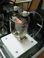
In the meantime my 833 is up and running smoothly. But because the weight is simply to much for bringing it to shows, audio-gatherings ets.....i'm making a small size 100TH-amp. It will weigh in at 55 kg/monoblock; so portable enough.
Pictures of the current building stage in next post.
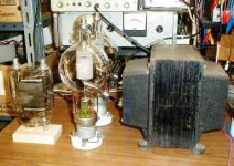
The 833's used in the ESL-amp are 833C's. These Chinese manufactures graphite anode can be had in 2 versions (at Penta Labs);
- 833C: 10 V / 10 A filament. But max anode dissipation of 500 W
- 833D: 10 V / 11.5 A filament. 600 W tube.
I only used the 833C; nice sounding. But not better than NOS Amperexes and the like; just different.
What i DID NOT like was that these tubes are extremely fragile. The first batch of 4 from the USA to the Netherlands all had broken filaments.
Regards,
Reinout
Hi all,
i did some postings in the beginning of this thread of my 833-amp. I'm so glad there are more nuts around (positivily meant).
The ESL-amp and the guitar-amp are just 2 examples that the 833 is simply GREAT !
In the meantime my 833 is up and running smoothly. But because the weight is simply to much for bringing it to shows, audio-gatherings ets.....i'm making a small size 100TH-amp. It will weigh in at 55 kg/monoblock; so portable enough.
Pictures of the current building stage in next post.
The 833's used in the ESL-amp are 833C's. These Chinese manufactures graphite anode can be had in 2 versions (at Penta Labs);
- 833C: 10 V / 10 A filament. But max anode dissipation of 500 W
- 833D: 10 V / 11.5 A filament. 600 W tube.
I only used the 833C; nice sounding. But not better than NOS Amperexes and the like; just different.
What i DID NOT like was that these tubes are extremely fragile. The first batch of 4 from the USA to the Netherlands all had broken filaments.
Regards,
Reinout
Attachments
Reinout, Your mechanical designs and workmanship are extraordinary. As I configure my 833 ESL amp into its final form, I will remember your work for inspiration, although I don't think that I have the mechanical skills you obviously have.
Sorry it's taken me so long to reply to a few questions about my ESL amp:
As Reinout correctly surmises above, these are Penta 833C graphite plate tubes, made in China. They are beautifully made, which is easy to see since the structures are so large and you can even look down inside the plate.
I saw them around my neighborhood too after the storms, and was tempted. But I didn't think Florida Power and Light, nor my wife, would approve.
I ordered those from Penta along with the tubes and the ceramic socket assemblies. I don't recall if they were a separate item or not. I think that there are other large tubes using the same diameter caps, so they may have been a generic stock item. They were a little roughly hewn. A friend put them in his lathe and turned them with abrasives to clean up the edges.
I've hesitated in the past to post the schematic (or just one of the many pages of schematics) for various reasons, but perhaps I can dredge up a "postable" version of the main circuit for you and post it here later. Output Z, going only by memory, is around 600 to 700 ohms (300 to 350 ohms per side of the output bridge). At the high voltages and low currents in an ESL (read: high impedance) that value of source Z is very low. To put it another way, these values exist in conditions that are equivalent to the conditions at the secondary of an ESL step-up transformer (which this amp replaces). If you were to step this source impedance back down by the Quad ESL-63's roughly 170:1 step-up ratio, 700 ohms is equivalent to an amp with an output Z of about 0.024 ohms (including cables and transformer losses). Said another way, I wanted to keep the "damping factor" very high so that the ESL amp acts like a voltage source at all frequencies to the ESL. With the Quads, I then added back a variable series resistor to re-voice the system. About 30Kohms sounded good to me, and that equates to about 1 ohm in the primary circuit.
Whose tubes are those? They look like graphite plates. All of the tubes I have use metal plates.
As Reinout correctly surmises above, these are Penta 833C graphite plate tubes, made in China. They are beautifully made, which is easy to see since the structures are so large and you can even look down inside the plate.
There were pole pigs just laying around in the street here after hurricane Wilma (pictures on web site). I thought about hauling one home, until I realized that I couldn't lift it.
I saw them around my neighborhood too after the storms, and was tempted. But I didn't think Florida Power and Light, nor my wife, would approve.
Brian, where did you get the heatsink topcap things for the 833As?
I ordered those from Penta along with the tubes and the ceramic socket assemblies. I don't recall if they were a separate item or not. I think that there are other large tubes using the same diameter caps, so they may have been a generic stock item. They were a little roughly hewn. A friend put them in his lathe and turned them with abrasives to clean up the edges.
where I can read the old description and the schematic that you had made? which value of Zout has the ampli?
I've hesitated in the past to post the schematic (or just one of the many pages of schematics) for various reasons, but perhaps I can dredge up a "postable" version of the main circuit for you and post it here later. Output Z, going only by memory, is around 600 to 700 ohms (300 to 350 ohms per side of the output bridge). At the high voltages and low currents in an ESL (read: high impedance) that value of source Z is very low. To put it another way, these values exist in conditions that are equivalent to the conditions at the secondary of an ESL step-up transformer (which this amp replaces). If you were to step this source impedance back down by the Quad ESL-63's roughly 170:1 step-up ratio, 700 ohms is equivalent to an amp with an output Z of about 0.024 ohms (including cables and transformer losses). Said another way, I wanted to keep the "damping factor" very high so that the ESL amp acts like a voltage source at all frequencies to the ESL. With the Quads, I then added back a variable series resistor to re-voice the system. About 30Kohms sounded good to me, and that equates to about 1 ohm in the primary circuit.
Hello Tubholics ! I've been reading very interesting things about all these very special tubes , thank you ! Would the 100TH work on the same way (A2 mode) , the 808 and some others Eimacs ? I have 20 pieces in the garage and would try a 307A in direct CF coupling for these . 😕 Your advice ? Thanks again cheers
ReinoutdV
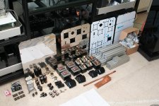
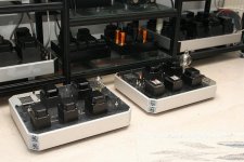
What type of chassis are you using? They seem to be modular in construction? Are these commercially available, and can they take much weight. I am working on some smaller monos which will tip the scale at about 100lb....
Thanks,
Bryan
What type of chassis are you using? They seem to be modular in construction? Are these commercially available, and can they take much weight. I am working on some smaller monos which will tip the scale at about 100lb....
Thanks,
Bryan
where I can read the old description and the schematic that you had made?
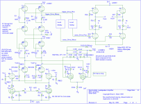
Here is one simplified version. There are several other pages of power supplies and details. Remember that this design is a test vehicle for ESL development, and it is overkill for Quads (although not in voltage levels needed at the peak). Some of the details will remain proprietary for now. I have since replaced the cross-coupled first stage with a simple 6SN7 diff amp using capacitive neutralization, but I don't have an image of that handy. I also have since doubled up in parallel the 6SN7s at the very top (connected to the 1000V supply) to allow more ability to transition into grid current (A2) for the 833s for very high voltage testing at the top of the audio band (not when driving the Quads!). Notice the DC coupling throughout.
I have found that with the Quads, I can bias the 833s at between 40mA and 50mA and the tubes will stay in Class A. That keeps dissipation for each tube at a happy 160 - 200W. But I can run them up to 100mA if needed for other purposes. The main reason for the use of the 833s is for the voltage capabililty. They also are quite linear as it turns out, and provide useful gain with a mu of 30 - 35.
The 150V floating supplies are regulated 1.7MHz switching supplies running either off AA cells or solar cells in a light box. No connection to the outside world (ie: low capacitance to ground) was allowed.
All of the many supply voltages are fully regulated, excepting the +/-4000 supplies which use massive C-L-C filtering. Bringing all these supplies up in the proper sequencing at power on required some timing tricks. So far, no fire works.
The double pentode servo diff amp keeps the outputs at both sides of the 833 bridge at close to zero volts at rest. It does this both differentially and in common mode at the same time. Since the lower 833's cathodes are referenced to the -4000 supply, any noise on the -4000 volt supply is picked up by the pentode servo and corrected at high speed (even though it would be common mode to the ESLs, I wanted it not to be a source of intermodulation). By contrast to the the fast common mode correction, differential "DC" drift is corrected slowly, only below the audio band, in true servo style. Note that the summing point for the servo is where the pentode plates connect directly in parallel with the 6SN7 plates. The plate impedance of the 12BY7 is so much higher than that of the 6SN7 that the 6SN7 hardly notices the impedance impact. The servos act as variable current sources. Interestingly, the measured DC offset at the output is usually only a few tenths of a volts, which would be similar to a few millivolts to a moving coil speaker.
The boxes marked simply "Level shifters" drop several thousand volts DC with a very low impedance using floating supplies that track fluctuations in the -4000 supply.
Signal feedback to the input is optional. I usually run it wide open.
Oh yeah, it measures very well and sounds great, but that's another story.
I doubt anyone else would be crazy enough to want to build one of these, but since you asked...
Attachments
Bryan said:ReinoutdV
What type of chassis are you using?
Hi Bryan. If I recall ReinoutdV is adapting components from a storage shelf system. I'm pretty sure he posted details elsewhere on the site.
Far out. I have a suitable output xfmer for my P-P 450TH amp!
Just finished listening to this very big hunk-o-iron clip leaded into a pair of 6L6's in a Eico HF-20 monoblock amp. This sounds as good as a REAL output xfmer (I'm talking full range listening on my big 8 ohm lab test speaker stack) and at WOT, (about 24 watts on this amp) the bass extends clean and flat to 10 Hz where my HP generator stops, better waveform than the actual eico output xfmer below 20 Hz. This confirms my earlier microwatt level testing of this big xfmer which looked very promising. The HV winding measures 35 Hy's and 60 ohms DCR plate to plate. Z Ratio is 8 ohms to 7k ohms plate to plate.
Just for a reality check I tried another big plate xfmer which is the same ratio and voltages, but which had much less Primary L (only 20 Hy's) and didn't measure as well on instrument testing. It sounded like absolute junk and the bass response was poor.
Here is a pic of my one prized piece of output iron, all ~100 lbs of it, a pair of 450TH's and an 833A for scale.
When I get started on this project I'll give ity it's own thread.
I wonder what I'll use as a P-P to P-P interstage xfmer?
This will be a fun project! 😀
Attachments
Hi Rcavictim ! How much uselif do you expect for your 450TH ? Do you prepare spares ? Why PP and not SE ? these will provide a huge output power , too much for daily use , especially on VOTTs ?! 😱 I forgot to talk about these "UFO" toobz like VT127A ? anybody knows ?
cheers ... Pierre
cheers ... Pierre
It is an order of magnitude easier to get an good output transformer for a PP amp than it is for an SE amp as there is no DC bias on the core.
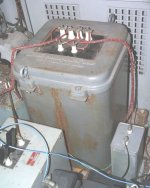
Heres a modulation transformer for a pair of class AB 833As plate modulating a pair of 833As in class C. Maybe ~4? times the power of a pair of 450TLs, but look at that hoss.
Heres a modulation transformer for a pair of class AB 833As plate modulating a pair of 833As in class C. Maybe ~4? times the power of a pair of 450TLs, but look at that hoss.
Attachments
coresta said:Hi Rcavictim ! How much uselif do you expect for your 450TH ? Do you prepare spares ? Why PP and not SE ? these will provide a huge output power , too much for daily use , especially on VOTTs ?! 😱 I forgot to talk about these "UFO" toobz like VT127A ? anybody knows ?
cheers ... Pierre
Pierre,
I have a spare pair of tubes but these tubes are readily available. Last time I priced them they were about $1,100.00 each US. That's cheaper than NOS WE 300B's! 😀 These toobz are used in commercial broadcast transmitters and give many thousands of hours service at full power.
I am going push pull for the highest output power and highest possible efficiency consistent with high fidelity. This amp (only one monoblock is being manufactured), is destined to power subwoofers It is not unusual to see 1 kW or more being used in a home system for this purpose, but sand is the only type of amplifier commercially available at these power levels. Bob Carver's Sunfire woofer has a sand amp that they call a 2,700 watt amplifier. Now if this operates on a 120 volt, 15 amp outlet then that power rating is pure marketing bovine, but it will still be mighty watty.
Now the way I figure it, to have one of the highest powered, purely tube sub amp in the world, triodes at that (!) could be of interest to someone. This amp I propose will output somewhere between one and two KW of real RMS toaster watts. It will be my output xfmer that is the power limiting component and only full power breadboard tests will tell me what it is really capable of.
The only way to get this kind of power out, is to put perhaps 50% more than that in. My amp will have to operate from a 220 volt circuit, like the stove or electric clothes dryer. That's no big deal for someone who is serious about tube audio, and who wants to keep it all tubes.
I can use an amp like this in my electronics lab as a variable frequency AC power supply or to power a shaker table.
I plan to sculpt it as art in case I decide to place it on the market once developed.
Tweeker said:
Heres a modulation transformer for a pair of class AB 833As plate modulating a pair of 833As in class C. Maybe ~4? times the power of a pair of 450TLs, but look at that hoss.
Tweeker,
Your post is a bit misleading. The 450 TL/TH triodes are higher power tubes than the 833A. They will handle 6 kV anode Vs 4 kV max for the 833A. They dissipate 450 watts CCS ( Continuous Commercial Service) versus 400 watts CCS (and only with forced air cooling) for the 833A.
If you are counting the power processed in the RF output stage beyond the P-P modulator pair, by a second set of 833A's then yes, four 833A's are handling more power than a pair of 450TL's.
There were a number of 1 kW AM broadcast xmitters that used four 833A's. They usually had a big window in the front cabinet panel door through which to watch the tubes. Is this transmitter you show one of your own toys? 😉 If so cool. That is a pretty big mod xfmer. Is that full of pourable PCB's or the tar kind? You should answer that question only in PM, not on this list. 😎
The 833A/C is a much better watt for your dollar investment in a big power triode for an audio amp. Spectacular bargain actually, and they are very, very good tubes. Sockets and mounting are a bit of trouble however.
Yes, its a tad misleading, I assumed that this threads readers would know dissipation on an 833A and 450TL. I made some assumptions here. That transformer is huge regardless of output power or modulator power, it has to carry the DC plate current for the pair of parallel SE RF tubes (in commercial service, reliabity paramount) and is thus outsized. This was mostly the point of my post. I was counting all 4 tubes as the transformer in effect has to carry all thier power. There is also lots of fudge contingant on the operating point of the 450TLs. The pair of PP 833A modulator tubes are driven by a pair of 845s so AB2 is my guess. The transformer is not mine, the photo was grabbed from the list. I think your right and it is an overbuilt 1kW setup, so I was off. I was trying to be conservative in relation to the iron. If I was a betting man Id say it is PCB iron, they didnt spare any expense on that thing.
Having DC on a transformer leads to saturation, requiring an air gap and and causing a drop in inductance and more leakage. So you need more turns, which then means more winding capacitance. Said turns also get further from the core leading to still more leakage. Mean turn length also increases. Your problem trying to get SE hi fi frequency response get exponentially worse as you scale up in power.
No kidding about the 833As, mine are a tad dodgy early NOS Chinese, but at $40 each shipped what can I say?
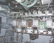
Heres your amp interior pic:
Having DC on a transformer leads to saturation, requiring an air gap and and causing a drop in inductance and more leakage. So you need more turns, which then means more winding capacitance. Said turns also get further from the core leading to still more leakage. Mean turn length also increases. Your problem trying to get SE hi fi frequency response get exponentially worse as you scale up in power.
No kidding about the 833As, mine are a tad dodgy early NOS Chinese, but at $40 each shipped what can I say?
Heres your amp interior pic:
Attachments
Tweeker,
You raised some good points describing the functions occuring simultaneously inside a modulation xfmer.
You raised some good points describing the functions occuring simultaneously inside a modulation xfmer.
Brian Beck said:
Oh yeah, it measures very well and sounds great, but that's another story.
I doubt anyone else would be crazy enough to want to build one of these, but since you asked...
Hi Brian,
thanks for the answers to the previous questions and for the present post with the schematic and comments. They are full of information and hint very interesting.
A lot interesting the input stage. I imagine that the greater problem is the balance of the output bridge.
There are also practical suggestions... is wily the idea of the variacs in order to obtain the transformer, high tension isolated, for filaments of the 833C.
Based on your experience, with what dissipation value, the graphite anode of 833C Pentalab, becomes a little red ?
Regards
HiG
______________________________
http://www.webalice.it/ansa_ht
password: 1,618 (Mozilla not Ok, sorry)
Based on your experience, with what dissipation value, the graphite anode of 833C Pentalab, becomes a little red ?
It depends on how dark the room is 😉
For most of my testing and listening, I set the bias so that each 833's plate dissipated about 160W, well below the max ratings. In a brightly lit room, I don't notice a glow (although you can make it out if look closely). With the lights off, there is a dull red glow. When I've cranked up the juice to 400 W per tube, a glow is apparent in a lit room. As long as you are within ratings for natural (non-forced) air flow, a glowing plate is no cause for concern. By the way, the hot graphite plate, in conjunction with coatings applied to it, acts as a getter, sucking up residual gases.
- Home
- Amplifiers
- Tubes / Valves
- Where are the 833 amps?