James D. said:
I love the Tesla coil pics - but they scare me! One of my jobs as a junior engineer with Decca was to help test their ceramic insulators. I had to stand in a huge Faraday cage with the insulator under test connected to a 500KW transmitter and then spray water over the insulator to cause rf arcing!!! Then the insulator was examined for damage. Great when it worked like that but every now and then the arc would come back down the water stream towards you... It would normally earth around you as one had rubber kit on and used a plastic water gun but it is dammed scary to have a mini lighting strike going on around you!!!
ciao
James
James,
I did some work for RacallDecca here in Canada some years back with broadcast antenna insulator testing. I got a chance to sit in on some testing in the US where they rented time on a decomissioned submarine ELF transmitting station converted to do HV RF testing. There was a half million watt xmitter there at ~30 KHz. It fed a HV generating resonating coil the size of a school bus wound with Litz wire that was the size of a broom stick handle. When they powered it up, if there was a ladbug or a fly anywhere on the HV buss it would launch a flare and they would have to shut down and then re-energize. Great electronic bug zapper! I am familiar with the water spray behaviour you spoke of (Mil spec water!). Interesting field, pun intended. 😀
Sorry for the off topic.
My 833 direct drive ESL amp
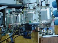
I hesitate to put this monster before you, because it is so insane, and not finalized in final form yet. But I’ve described it elsewhere in DIYAudio, so I’ll be brief here. Several years ago I built a direct-drive amplifier for electrostatic loudspeakers (ESL) using 833s. These tubes directly connect to the ESL stators without transformers or coupling caps. The 833s drive Quad ESL-63s happily, bypassing both any OPT but also the step-up transformers in the Quads. However I went all out on this amp because I needed a test source for a new ESL design project I’m involved in. It was also a test bed for several design ideas. It’s totally insane, impractical, unsafe and very hot, of course. Each channel uses four 833s in a SRPP bridge running off +/- 4000 supplies. Output is 4800 V rms, or 6800 V zero-peak.
I will post pictures of the breadboard version only for now. The final configuration is a stereo pair housed in half-height rack chassis, one chassis per channel. A glass enclosure will keep fingers away from high voltages, and act as a plenum for forced air cooling, required due to eight 833s in the room dissipating 2000W. A dedicated A/C supply duct and a return duct will be routed, so that heat will not directly impact the listening room, a necessity here in Florida. However, home renovation, followed by two hurricanes, and now a move has conspired to halt final configuration progress.
Here is one channel's worth of tubes cooking.
Attachments
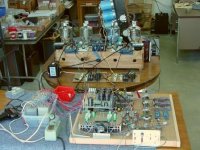
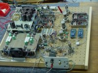
This picture shows the breadboard of one channel. The input circuits are up front; the 833s are farther back. Behind the 833s, barely visible and leaning at an angle for servicing is the +/- 4000 volt supply. The 100 lb. transformer for the HV is from a Collins T-368 transmitter. It's bigger than a car battery. I was lucky to snare a pair of these beasts.
Attachments
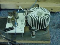
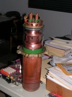
I used the cores from salvaged 300VA variacs as my filament transformers. I kept the primary intact and wound 15KV-rated silicone insulated wire around the core to achieve 10VAC at 10A for each tube. The cathodes swing at high voltages so the high voltage wire was necessary. This picture shows one such transformer connected to a test socket. The final eight filament transformers are sandwiched in a elastomeric clamping arrangment to keep the secondary windings from buzzing around.
Attachments
Brian,
You are one hip dude! My kind of DIY'er. Hats off and all that. I hope you have current limiting between the amp and the electrostatic speakers to prevent possible explosions and fire.
I'm planning quite an amp at the moment using a pair of 450TH's in push pull making as much as 2 kW audio power but as far as pushing the envelope, it won't even come close to how radical this thing you have conceived is. Nice! Hope it doesn't hurt anyone, ever.
My 'probable' P-P 450TH subwoofer amp
I am renewedly examining the possibilities of making a very high powered monoblock for primary application as a subwoofer amp as mentioned above Tube candidates are a pair of Eimac 450TH's in push pull. Key to this is of course getting a suitable hunk of iron that will work as an output xfmer. I wasn't sure until today but I think I have that covered. Yipee!
I have a huge Hammond plate xfmer with heavy cast end bells and a house project number so I cannot look up specs. It has 1710-0-1710 HV secondary and primary with 0-100-105-110-115-120 volt taps. Turns out 120 volts into an 8 ohm load is about 2 kW so that is right in the ballpark of the output that this amp will have. Turns ratio makles 8 ohm load appear as ~7 k ohms plate to plate which couldn't get much better if I ordered a real o/p xfmer. DCR is only 60 ohms across the entire HV winding. Primary L is high at 34.6 Henries. That is what I need for good bass response. There is a lot of iron here. It weighs about 100 lbs. It came from a WW-II xmitter. I have been packing this thing with me since high school. Bloody glad I did!
I just finished doing frequency response testing by putting the 600 ohm o/p of my HP audio oscillator through a 6.8k R to the full HV winding and loading the 120 volt secondary with 4 and 8 ohm R's and watching the response on the o-scope. Ruler flat from 40 Hz to 8 KHz. Response at 15 Hz only down about 1 dB. It looks like with NFB this will make full spectrum. 15+ KHz at the high end. I replaced the generator with a CD player and the o-scope with an audio amp and speakers. At microwatt power levels the transformer sounds pretty good on full range. I had to boost the treble on the monitor amp but that brought the highs back.
Just for curiosity I grabbed a similar but smaller (700 VA) Hammond plate xfmer, same secondary voltage, somewhat newer and it only had 25 Hy's primary L. I wouldn't be surprised if my huge one was wound for 25 Hz. That makes it a rare chunk-o-iron indeed and better suited for my application.
As far as a HV PS capable of delivering enough for a pair of 450TH's making 1.5 to 2 kW output I am all set. I have a complete HV power supply I got from a hamfest sale of some of Fred Hammond's personal ham effects. It contains a big 2000-0-2000 volt plate xfmr rated at 2.25 kVA. I forget the make...oh yes Hammond. 😀 Also has SS diodes good for the job, a suitable huge choke and filter cap bank and bleeder R. Including 450TH tubes and their odd 7.5 volt, 20 amp filament xfmr's (which I grabbed with the tubes out of some xmitters I stripped) I have all the expensive parts to make one only of these wacky monoblock amplifiers. Might as well!
I'll begin by breadboarding the output stage and PSU then do tests driving the beast with a variac and split winding power xfmr for P-P grid drive at 60Hz. If this looks good I'll design a xfmer coupled driver, P-P of course, later.
Now I'm far from being an expert in these matters of tube amps and output xfmers and build stuff very successfully most of the time based a lot on instinct. My hands seem to be pretty smart. The bench breadboard will tell me ultimately if this is a go or no-go idea but if there is something about this reapplicated plate xfmr that I'm not seeing feel free to step in and comment.

That is seriously frightening. What are the 9-pin tubes?
It IS seriously frightening. I have a lot experience as an engineer in the RF world, so I have a deep respect for high voltages. I always had a buddy (also experienced) with me during development testing. We'd keep an eye on each other to make sure we didn't let an elbow stray too close to a plate cap, for example.
9-pins? I experimented with various first stage configurations, trying 6922 cross-couplers, 7119 diff amps and lastly 6SN7 tubes throughout. The last choice is probably the best. The whole thing is differential from input to stators. The other 9-pin tubes are 12BY7As used for housekeeping - current sources and a pentode servo amp with controlled amounts of both common-mode and differential-mode feedback for DC stability.
I hope you have current limiting between the amp and the electrostatic speakers to prevent possible explosions and fire.
No, not yet. The final configuration will have output error sensing circuits and fast-acting Jennings HV relays to disconnect HV if a problem develops.
Tweeker,
You are cut from different cloth...
I think we could have much fun making explosives...
:devil:
You are cut from different cloth...
I think we could have much fun making explosives...
:devil:
Brian:
I remember you describing this amp to me a while back. I failed to realize the scope of this project until you posted the pictures. That has got to be the most over the top home brew stereo system that I have seen. Undisputed king of the 833 amps.
Whose tubes are those? They look like graphite plates. All of the tubes I have use metal plates.
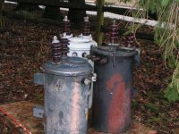
It looks like you have awakened the "Montster amp Garage" in a few readers. Maybe there will be some more killer amps to report on in the future. There were pole pigs just laying around in the street here after hurricane Wilma (pictures on web site). I thought about hauling one home, until I realized that I couldn't lift it.
I remember you describing this amp to me a while back. I failed to realize the scope of this project until you posted the pictures. That has got to be the most over the top home brew stereo system that I have seen. Undisputed king of the 833 amps.
Whose tubes are those? They look like graphite plates. All of the tubes I have use metal plates.
It looks like you have awakened the "Montster amp Garage" in a few readers. Maybe there will be some more killer amps to report on in the future. There were pole pigs just laying around in the street here after hurricane Wilma (pictures on web site). I thought about hauling one home, until I realized that I couldn't lift it.
"I thought about hauling one home, until I realized that I couldn't lift it."
Thats the sticking point with pole pigs. I cant deal well with anything over about 25kVA due to weight. Ive been collecting 50amp 1156D variacs to use with pigs to avoid the costs of "plate transformers". Pigs are nice in that they can be found for a few dollars/kVA, unlike anything that involves the word "tube".
The tube on the table in the office is a GU-23A 60kW triode, its really not ideal for my purpose, especially given the iron I have on hand. If I use it, it will probably be as a linear amplifier. Im considering buying a pair of GU-39 8kW tetrodes and screen modulating them instead. As always, funding is an issue.
Brian, where did you get the heatsink topcap things for the 833As?
Tweeker said:Final stage for plasma guitar project:
What's the basic idea. strike a chord and generate steam? 😀
That tube looks like a 50 kW job. You only have 30 kVA worth of pole xfmers. Good plan. Extra tube life! 😉
It is pretty much run like an AM transmitter, except instead of driving an antenea I drive a coil and an RF arc. The arc is modulated with audio giving the sound. Its grossly inefficient, and worse as the frequency drops, Im seeing how low I can go by throwing sheer power at it.
Ive actually got 4 pigs, but was planning on using a 3 phase power for easier filtering. It would be nice if I could find a set of 4160V pigs so I could make a 12 pulse rectifier. It would also be nice if I found a few Picasso paintings in the attick.
Ive actually got 4 pigs, but was planning on using a 3 phase power for easier filtering. It would be nice if I could find a set of 4160V pigs so I could make a 12 pulse rectifier. It would also be nice if I found a few Picasso paintings in the attick.
Re: My 833 direct drive ESL amp
Hi Brian
Whooow... mine compliments, all-beautiful !!
where I can read the old description and the schematic that you had made?
which value of Zout has the ampli?
regards
HiG
______________________________
http://www.webalice.it/ansa_ht
password: 1,618
Brian Beck said:I hesitate to put this monster before you, because it is so insane, and not finalized in final form yet. But I’ve described it elsewhere in DIYAudio, so I’ll be brief here. Several years ago I built a direct-drive amplifier for electrostatic loudspeakers (ESL) using 833s. These tubes directly connect to the ESL stators without transformers or coupling caps. The 833s drive Quad ESL-63s happily, bypassing both any OPT but also the step-up transformers in the Quads. However I went all out on this amp because I needed a test source for a new ESL design project I’m involved in. It was also a test bed for several design ideas. It’s totally insane, impractical, unsafe and very hot, of course. Each channel uses four 833s in a SRPP bridge running off +/- 4000 supplies. Output is 4800 V rms, or 6800 V zero-peak.
I will post pictures of the breadboard version only for now. The final configuration is a stereo pair housed in half-height rack chassis, one chassis per channel. A glass enclosure will keep fingers away from high voltages, and act as a plenum for forced air cooling, required due to eight 833s in the room dissipating 2000W. A dedicated A/C supply duct and a return duct will be routed, so that heat will not directly impact the listening room, a necessity here in Florida. However, home renovation, followed by two hurricanes, and now a move has conspired to halt final configuration progress.
Here is one channel's worth of tubes cooking.
Hi Brian
Whooow... mine compliments, all-beautiful !!
where I can read the old description and the schematic that you had made?
which value of Zout has the ampli?
regards
HiG
______________________________
http://www.webalice.it/ansa_ht
password: 1,618
Tweeker said:It is pretty much run like an AM transmitter, except instead of driving an antenea I drive a coil and an RF arc. The arc is modulated with audio giving the sound. Its grossly inefficient, and worse as the frequency drops, Im seeing how low I can go by throwing sheer power at it.
Ive actually got 4 pigs, but was planning on using a 3 phase power for easier filtering. It would be nice if I could find a set of 4160V pigs so I could make a 12 pulse rectifier. It would also be nice if I found a few Picasso paintings in the attick.
Not your everyday hobby for sure. In the past I have played around with audio modulated RF plasmas and tesla coil discharges in atmospheric air and argon at atmospheric pressure but only up to a few kW's of HV RF. I figure I know enough to make an interesting plasma speaker but just don't have the time to play with all my ideas.
- Home
- Amplifiers
- Tubes / Valves
- Where are the 833 amps?