I did a patent search decades ago and found a simple OTL that was patented in the early 1950s. I built it up for fun and it seemed to work. Much simpler circuit than either the Futterman or Circlotron types. It was a totem pole design. I don't remember the inventor.
I'd be interested to hear about pre-Futterman OTL amp designs.
Yes. There was a model built by Philips using two EL86, a coupling capacitor and a 800 Ohms speaker. Something similar to this :
The Futterman circuit uses a direct coupling to the speaker, which is 8 to 16 ohms :
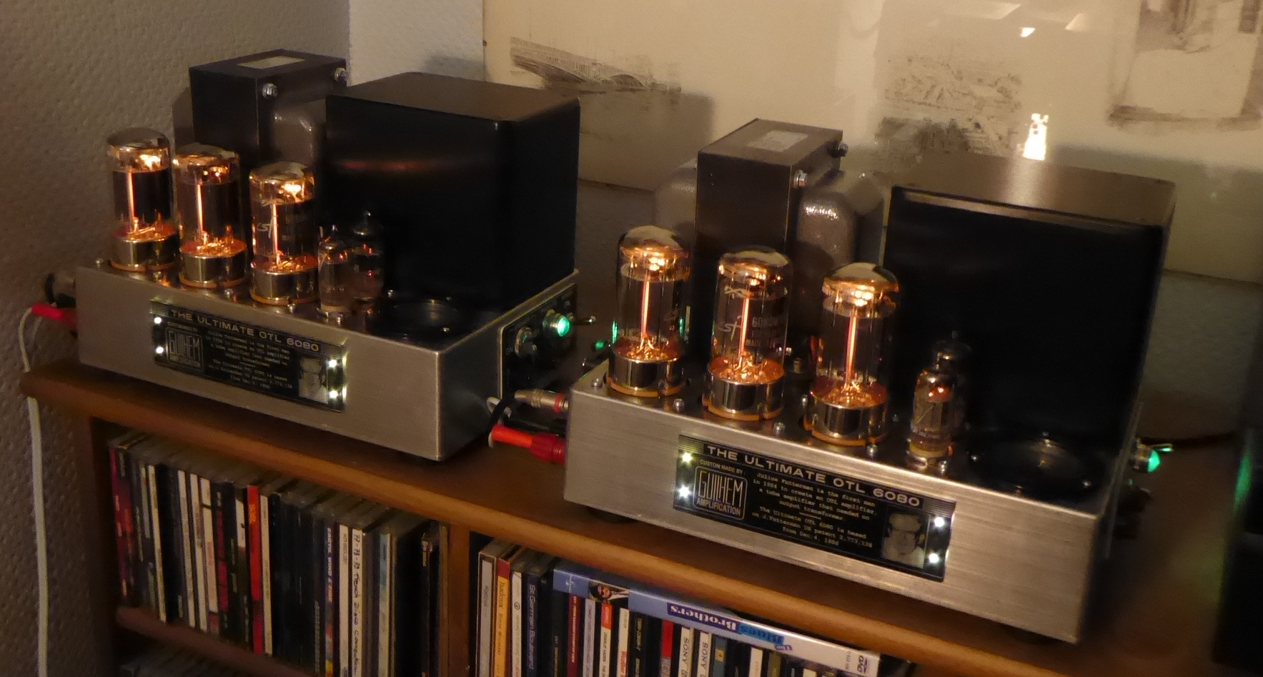
They are so cute!
Thanks @atmasphere ! Compactness is always a target for me...
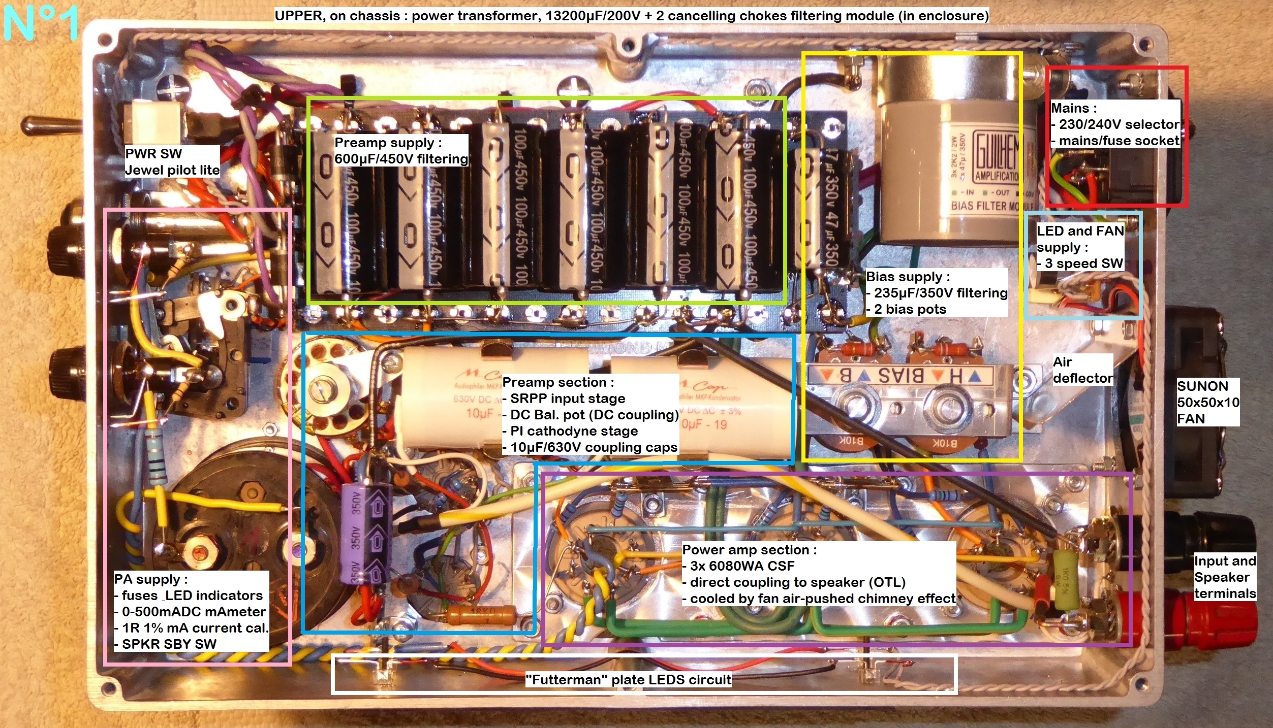
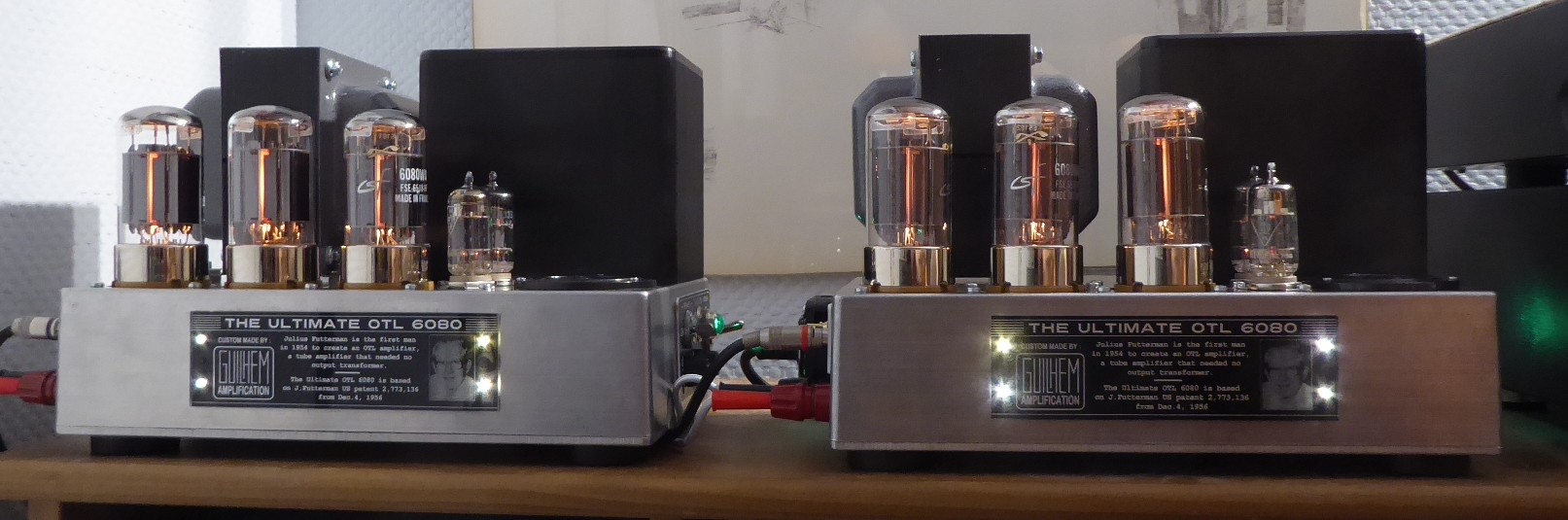
My U-OTL are the application of the Futterman patent, with some modern (and securitive) features, like a power transformer providing the output stage plate voltage, etc. But still completely tubes, not hybrid.
Performances are :
- Output power = 10WRMS @16R (clipping at 12-13W) for 0.675VRMS input sinus,
- Bandwidth = 1Hz-200kHz @ -3dB/10WRMS/16R.
- THD = not measured, no metering available for the moment. Simulations by member @Brice gave less than 1% IIRC at 10WRMS 16R.
- No global NFB loop.
Square waves at 10WRMS 16R :
T

I have no idea why but when quality, compactness and a good eye to aesthetics appear in the same package its always lovely to me. Good job!!Compactness is always a target for me...
Now what could be simpler than a Futterman H1:I did a patent search decades ago and found a simple OTL that was patented in the early 1950s. I built it up for fun and it seemed to work. Much simpler circuit than either the Futterman or Circlotron types. It was a totem pole design. I don't remember the inventor.
A current starved pentode input
a cathodyne splitter
and a totem pole output ?
... maybe a self splitting output .... but "much" simpler ... ?
Here's an article which covers the historic attempts to otl amplification with basic archtecture, inventors and literature references:
part 1: http://www.r-type.org/articles/art-153.htm
part 2: http://www.r-type.org/articles/art-146.htm
Thanks for the links - that was fun to explore.
It appears that Fletcher/Cooke ['Electronics' Nov 1951] and Brociner/Shirley ['Audio Engineering' June 1952] both had true OTL designs for standard impedance drivers that pre-dated Futterman.
It appears that Fletcher/Cooke ['Electronics' Nov 1951] and Brociner/Shirley ['Audio Engineering' June 1952] both had true OTL designs for standard impedance drivers that pre-dated Futterman.
I wanted to update my earlier post:I am using the 2-tone test where the Upper tone's amplitude is 25% of the lower tone. The tones are 60hz and 3khz. The upper tone is distorted by the lower tone.
Feedback resistor changed from 2megs to 100k removes 95% of the distortion. Lower than that removes most of the gain.
I am using an 8ohm speaker as a load rather than a resistor, but switching to a 8ohm resistor does not change it much.
Clarity in the upper octaves is improved greatly with more FB.
Russ
I settled on 150K ohm for the feedback resistor. This increased the IMD by about .3% to a little over 1% at 1 watt, but it evened out the dip the 100K had created in the midrange. It was only about 1db.
I am very happy with the results. I could see that a person might want to go as high as 200K but IMD would be above 2%.
Harmonic distortion seems to be about .3% at 1W tested from 10 hz to 100khz with HD at 4hz being around .6% (which might be because of my antique Heathkit test equipment's limitations). It is cool to watch a speaker doing 4hz 🙂
I will post some of my measurements once the comparison between the M-60 clone and my 2 Futterman amps is completed. Honestly the clone would have failed this challenge without the increased feedback. (By listening alone)
As to tubes, the GE 6SN7s seem to have a bad rep when it comes to IMD but I could not prove it in testing. In the next couple of days I can roll in some Sylvanias. I have all BUT the fabled 1952 version. I also have enough TS-tall to equip one channel, but compared to the FB change, I don't expect much. My build requires 10 6SN7s to equip both channels.
I was listening to Sail by AWOLNATION last night. It is amazing what good bass can sound like when it comes to "modern" music. The recording has plenty of harmonics built in which seem to be on the same harmonic freq. as those generated by the window behind me. Maybe I should turn it down - but I probably won't.
Russ
Last edited:
Have just finished up a single M-60 mono block I have built up from a bunch of parts from someone here in NZ many years ago, I initially finished this a couple of years ago but when i went to test it had pretty much zero gain and i only had a home theatre amp as a source which i thought was my issue and have recently got a couple of tube preamps (Conrad Johnson PV10a & Sonic Frontiers SFL-1) but it turned out I had the single RCA input splitting across both balanced input pins (1 & 4) on V1 instead of just to pin 1 and then having pin 4 to the ground of the input as per XLR shorting plug design!
The build is a bit of a hybrid of the information contained in this forum and now I'm getting back into it I see there have been some updates, still have a couple of things to tidy up due to finding that issue yesterday and I have roughly connected those up, have left out the A/AB selection but something i would love to know is the reason for the feedback switch, which is shown in some diagrams and not others? I currently don't have one fitted but is easy enough to add, i also don't have a DC balance switch or meter installed and have tried to set this using a digital multi meter for the moment without much luck at getting in spec? Was trying to find a nice meter to use for this but couldn't find one when I was looking a while back so I better resume that search.
I also need to add a second switch so i can tuned the heaters on before the high voltage stage but currently it appears to function perfectly fine.
You will notice the two big capacitors which are 3400uf 350v for the Bridge1 & Bridge2 supplies, I used these as I had them but these will probably be something that could be upgraded in the future as I see most builds are using 1000uf quads for this! I did pick up some 2200uf 200v PCB mount caps at a flea market that I might use once I make a version two case! Couple of pics attached. Cheers
Solid performance!Yes. There was a model built by Philips using two EL86, a coupling capacitor and a 800 Ohms speaker. Something similar to this :
View attachment 1391316
The Futterman circuit uses a direct coupling to the speaker, which is 8 to 16 ohms :
View attachment 1391317
View attachment 1391318
Thanks @atmasphere ! Compactness is always a target for me...
My U-OTL are the application of the Futterman patent, with some modern (and securitive) features, like a power transformer providing the output stage plate voltage, etc. But still completely tubes, not hybrid.
Performances are :
- Output power = 10WRMS @16R (clipping at 12-13W) for 0.675VRMS input sinus,
- Bandwidth = 1Hz-200kHz @ -3dB/10WRMS/16R.
- THD = not measured, no metering available for the moment. Simulations by member @Brice gave less than 1% IIRC at 10WRMS 16R.
- No global NFB loop.
Square waves at 10WRMS 16R :
View attachment 1391325
View attachment 1391326
View attachment 1391331
View attachment 1391329
View attachment 1391332
View attachment 1391333
T
@fabio1983
The feedback switch was sometimes an option. I'd leave it out and run the feedback.
We typically ran 6600uf per bridge supply. The earlier amps used a smaller value. We had it spread out between 3 filter caps of 2200uf each. That allowed us to install a 1 Ohm 5 Watt resistor between the input of the supply and the remaining 2 caps, rounding off the top of the sawtooth waveform a bit. When the amp is properly balanced, the sawtooth cancels so isn't heard.
The Mk3s all used a 5 Ohm cathode current limiting resistor rather than 1 Ohm.
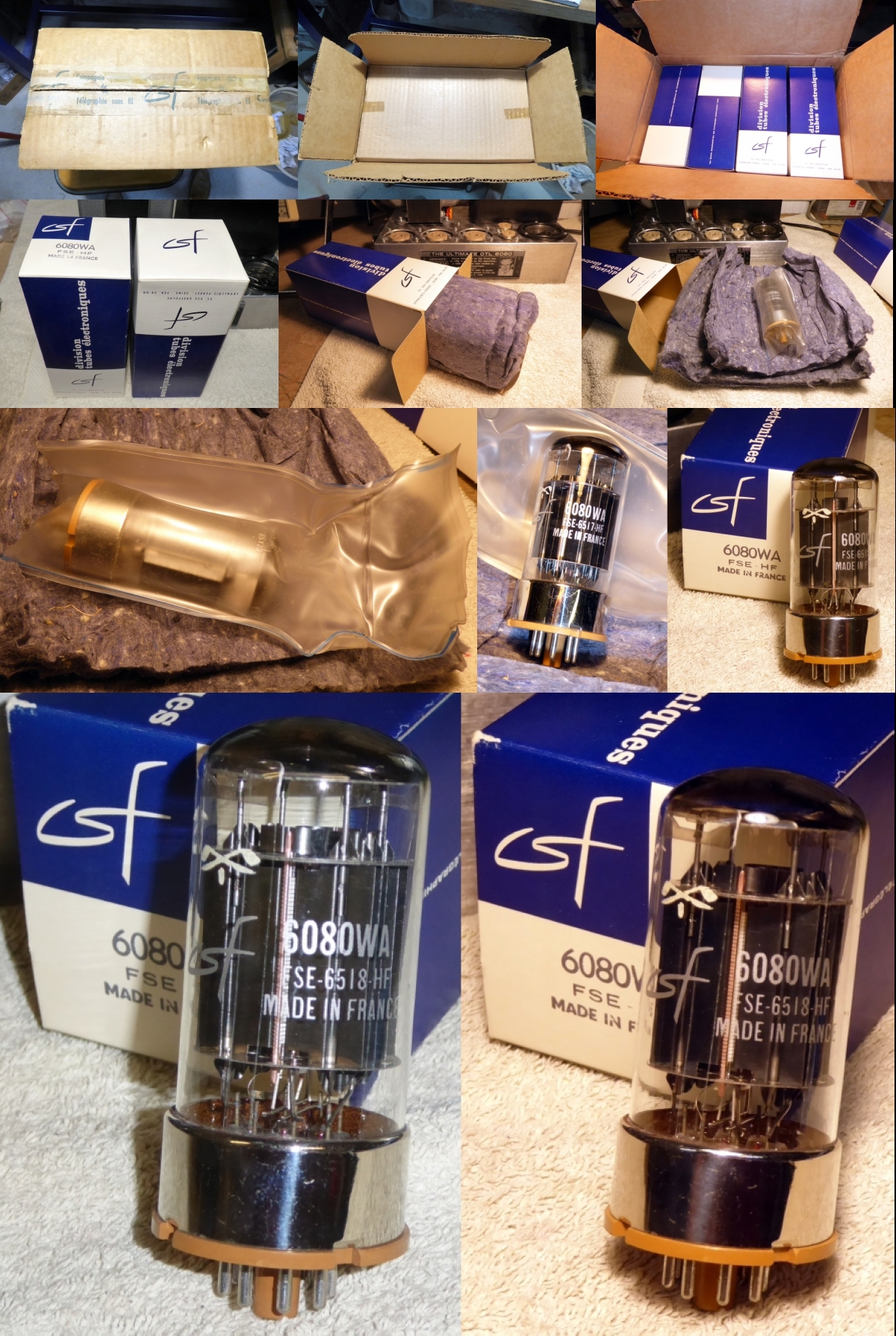
What tubes for a OTL tube amp?
I still rely on the faithfull 6080WA :
T
These Thomson are amazing; would love to build a headphone OTL with them.
@atmasphere
Thanks for your reply! The 200v 2200uf ones I have should be suitable then? I don't have a scope to check a few things and I do have a noise that is very much like a sawtooth when I make one in a sound generator! When I connect my multi meter across the speaker terminals this noise does reduce, if using the multi meter to set the DC offset i should be aiming for 0?? (in mA setting?)
I will update the cathode current limiting resistors to 5 Ohm for my next block build.
@atmasphere
Thanks for your reply! The 200v 2200uf ones I have should be suitable then? I don't have a scope to check a few things and I do have a noise that is very much like a sawtooth when I make one in a sound generator! When I connect my multi meter across the speaker terminals this noise does reduce, if using the multi meter to set the DC offset i should be aiming for 0?? (in mA setting?)
I will update the cathode current limiting resistors to 5 Ohm for my next block build.
@fabio1983 : are you sure that your wiring may not held some culpability in this oscillation by an unsuspected coupling ? Despite that, even with an as short and as logical wiring as possible, the 6AS7 and the 6080 may need a 1500R grid stopper resistor when paralleled : that's what I noticed several times...
T
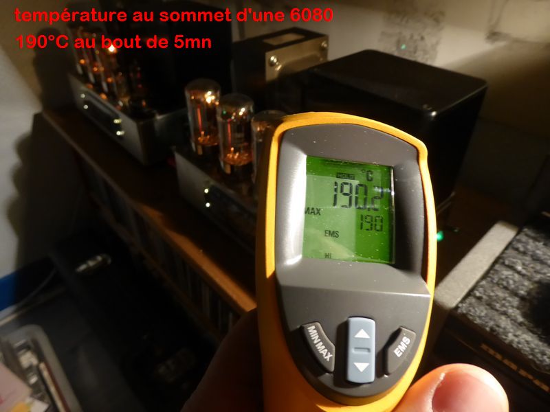
Something I noticed, is how hot the inside of a closed chassis can get from the 6AS7s. Even with them mounted on top. If you leave the bottom open it might be OK. But I would point a laser thermometer at those filter caps after about half an hr - both the caps on top and the ones underneath.Have just finished up a single M-60 mono block I have built up from a bunch of parts from someone here in NZ many years ago, I initially finished this a couple of years ago but when i went to test it had pretty much zero gain and i only had a home theatre amp as a source which i thought was my issue and have recently got a couple of tube preamps (Conrad Johnson PV10a & Sonic Frontiers SFL-1) but it turned out I had the single RCA input splitting across both balanced input pins (1 & 4) on V1 instead of just to pin 1 and then having pin 4 to the ground of the input as per XLR shorting plug design!
The build is a bit of a hybrid of the information contained in this forum and now I'm getting back into it I see there have been some updates, still have a couple of things to tidy up due to finding that issue yesterday and I have roughly connected those up, have left out the A/AB selection but something i would love to know is the reason for the feedback switch, which is shown in some diagrams and not others? I currently don't have one fitted but is easy enough to add, i also don't have a DC balance switch or meter installed and have tried to set this using a digital multi meter for the moment without much luck at getting in spec? Was trying to find a nice meter to use for this but couldn't find one when I was looking a while back so I better resume that search.
I also need to add a second switch so i can tuned the heaters on before the high voltage stage but currently it appears to function perfectly fine.
You will notice the two big capacitors which are 3400uf 350v for the Bridge1 & Bridge2 supplies, I used these as I had them but these will probably be something that could be upgraded in the future as I see most builds are using 1000uf quads for this! I did pick up some 2200uf 200v PCB mount caps at a flea market that I might use once I make a version two case! Couple of pics attached. Cheers
View attachment 1400604View attachment 1400605
I used some 3.3uf 630V Solens to couple stages on my Futterman/Glass Audio/Pete M./ME 4-tube version (per channel) and it got hot enough inside the chassis to re-shrink the shrink wrap on the Solens. Too hot. I had to add a fan to that one. Modified the build later.
P.S. Half an hr. on stand-by won't equal the heat generated when it is really doing something.
BTW mine has much better distortion stats after it gets really warm.
Last edited:
Gotta wonder how the tubes stay alive. 150 volt rails for maybe 10w of power.
Throw some FM or compressed modern stuff into it and you will red plate at 2w .
Throw some FM or compressed modern stuff into it and you will red plate at 2w .
@tubelectron@fabio1983 : are you sure that your wiring may not held some culpability in this oscillation by an unsuspected coupling ? Despite that, even with an as short and as logical wiring as possible, the 6AS7 and the 6080 may need a 1500R grid stopper resistor when paralleled : that's what I noticed several times...
T
Yes there could be some interference from the wiring, the noise doesn't change based on preamp volume so I do suspect it could well be in the Bridge1 & 2 sections as I am only using the one large capacitor in each with no secondary filtering and it would be about a 60hz hum which is our AC frequency here in NZ, still have a second mono block to build so going to make that change with the next one.
@phlogistonSomething I noticed, is how hot the inside of a closed chassis can get from the 6AS7s. Even with them mounted on top. If you leave the bottom open it might be OK. But I would point a laser thermometer at those filter caps after about half an hr - both the caps on top and the ones underneath.
I used some 3.3uf 630V Solens to couple stages on my Futterman/Glass Audio/Pete M./ME 4-tube version (per channel) and it got hot enough inside the chassis to re-shrink the shrink wrap on the Solens. Too hot. I had to add a fan to that one. Modified the build later.
P.S. Half an hr. on stand-by won't equal the heat generated when it is really doing something.
BTW mine has much better distortion stats after it gets really warm.
I have noticed how hot the case gets even with the bottom open, am going to redesign the layout and have some vent holes added around the 6AS7s and reposition the transformers on top so its more balanced and then will have a new arrangement for capacitors underneath instead of the two beasts i currently have!
If all there is in one of the bridge supplies is 2200uf it will work but you'll hear it sounding better (particularly at higher volumes) with double or triple that value.@atmasphere
Thanks for your reply! The 200v 2200uf ones I have should be suitable then? I don't have a scope to check a few things and I do have a noise that is very much like a sawtooth when I make one in a sound generator! When I connect my multi meter across the speaker terminals this noise does reduce, if using the multi meter to set the DC offset i should be aiming for 0?? (in mA setting?)
I will update the cathode current limiting resistors to 5 Ohm for my next block build.
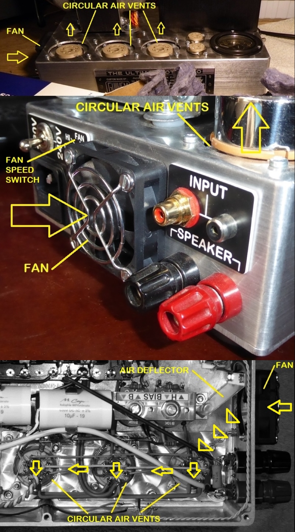
If you look at an actual M-60 chassis they have a lot of cooling holes- there is a pattern of holes around each power tube. The bottom cover has slots as well and the power supply cover has more.
With the 5 Ohm resistors if a power tube shorts its less likely to blow the links in the base of the power tube. This can result in the amplifier pushing a fair amount of DC current. So its important to pay attention to the fuse rating of the B+ transformer and in the case of lower power full range drivers an inline fuse is recommended. That's a good idea for such speakers any time the amp can make more power than the rating of those drivers.
The chassis should be grounded to the ground connection of the AC power cord. To this end, all of the audio grounds should not touch the chassis. A resistance can be placed between the two so the audio ground floats at chassis potential. In this way the chassis will not contribute noise to the audio circuit.
Something I noticed, is how hot the inside of a closed chassis can get from the 6AS7s. Even with them mounted on top.
Yes. These tube '6080 and 6AS7) must not be underrated about temperature and heat...
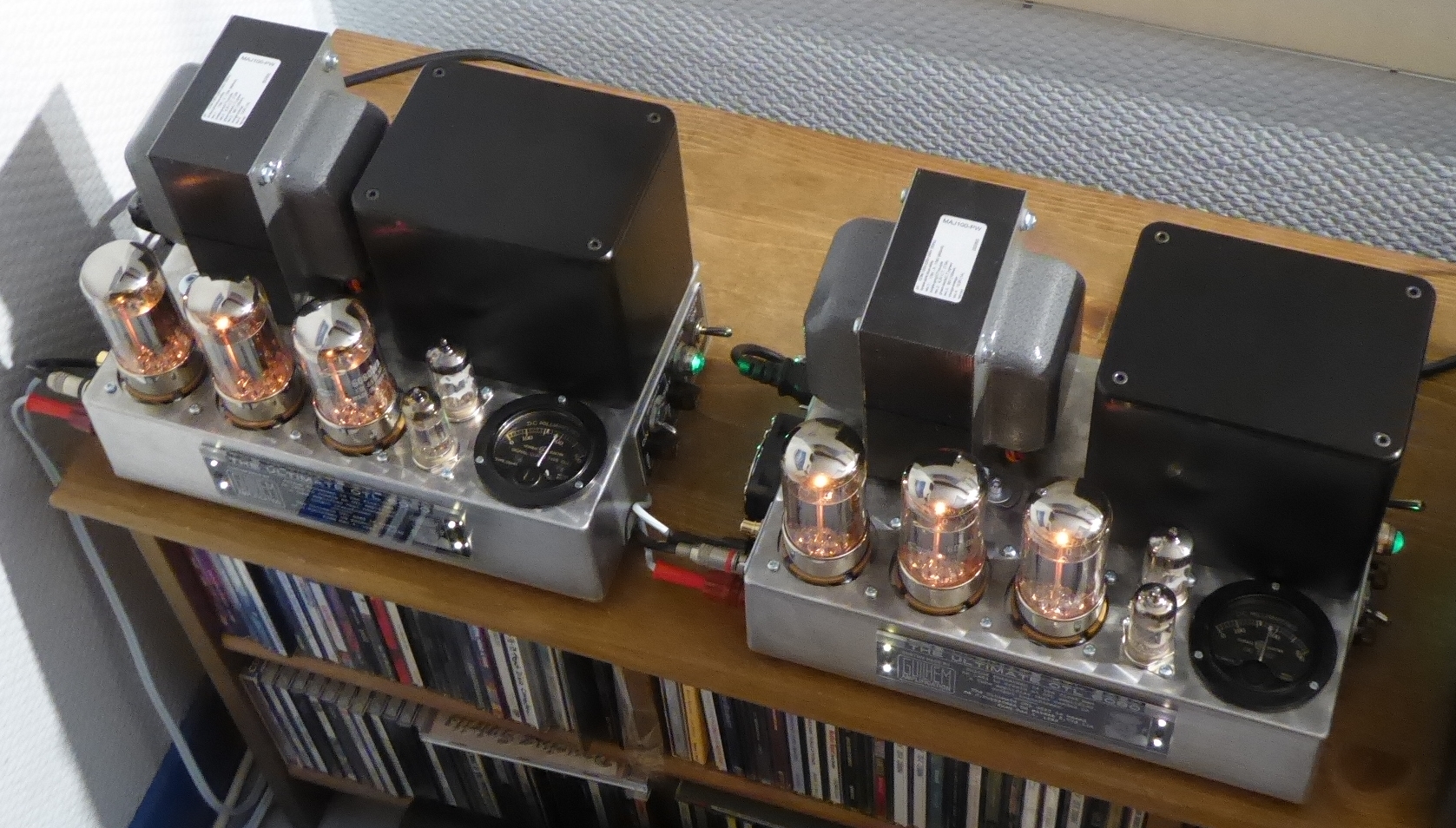
Here is the measured temp (°C) on the top a 6080 in my U-OTL :
Here's the cooling system I installed, and it works perfectly, even at slow speed, unheardable fan :
T
Some people prefer OTL amplifiers.
Those square waves look classically perfect. Now, get a test CD, and look at the square waves, they are not classically perfect.
Need Hernia insurance.
Need an air conditioned room in fall, spring, and summer.
Need suitable speakers.
Mant quality output transformers are better than most loudspeakers. Throw those quality output transformers into the trash (no, ship them to me).
Connect an amplifier to a Klipsch LaScala or a Quad electrostatic speaker, and what do you see inside . . . signal transformers.
Many other loudspeaker models do that too.
There are many many more output tubes that are very well suited for Single Ended amplifiers and Push Pull amplifiers that employ an output transformer.
Many of those good tubes are not well suited for OTL amplifiers.
All is a tradeoff.
I hope 2025 finds good examples of OTL amplifiers, and finds good examples of amplifiers that employ output transformers.
OTL continuum,1,198 posts, and counting.
$0.03
Adjusted for inflation
Last edited:
What the world needs is a 1st Watt OTL Amp that transitions smoothly to a standard P-P Amp at higher power. No heat wave and a limited # of output tubes. Something like a CFB Amp where the plates are mostly inactive until above 1/2 a Watt output (across the CFB winding). Just enough plate winding drive component in the low Watt range to null out the CFB winding loading. Then transitions progressively to full CFB P-P output at higher power. Use some big honker TV Sweeps for the CFB winding drives and more conventional KT-- tubes for the plate winding drives. ( just biased down so they join in around 1/2 W output level. ) 1 Watt OTL with 45 Watt full P-P power.
Last edited:
I am very pleased with the clarity of this amp with the listening i have done i must say, this is my first project of this kind! The speakers I am driving are based on the ETI-4000 (12" woofer, 8" low/mid, 4" high & 1" dome) design which my dad built back in the 80's and i have tidied up this year so i have no idea of their sensitivity!
- Home
- Amplifiers
- Tubes / Valves
- What tubes for a OTL tube amp?