They didn't understand the implications of the Reynolds number. Once that was sorted the math works fine for bumblebees. The myth about the math persisted for decades after the issue of the Reynolds number was sorted.According to early engineers and physisists, the bumblebee was not capable of flying, but further studies proved that it can fly.
I don't know who came up with that idea but it was clearly wrong. My Scully lathe with Westerex 3D cutter head and electronics was bandwidth limited at 42KHz by means of a bandwidth filter built into the mastering amps. Then there's a 30dB feedback loop around which is nested the mastering amp. When you have that kind of feedback at all frequencies the distortion is very low- much more so than most digital mavens care to admit. Most of the distortion of LPs occurs in playback. Most of the 'studies' about LP distortion date from the 1960s or 1970s before a lot of issues of tonearms and cartridges were really sorted out.Vinyl records, and the super small stylus contact area, and other factors, should not sound very good.
WRT an OTL driving a speaker as the one mentioned the issue is whether or not the amp uses enough feedback to behave as a Voltage source, (which in the case of our OTLs they don't) and whether the speaker is intended to be driven by a Voltage source (which most are). If you have a speaker that was made prior to the adaption of the Voltage rules (perhaps an Altec from the 1950s) then its using the Power rules instead. Such speakers are rare today but they do exist. So in your scenario, the question is whether or not the amps and speakers are playing by the same rules. If they are no worries, if they are not you will get a tonal imbalance. You can read more about this here.

atmasphere,
Thanks!
Lots of things to think about.
First of all, my first read of your document went well. It will not be the last time I read it.
When I consider the various amplifier output characteristics, I put them into 4 categories:
1. Voltage Amplifiers, very low output impedance.
2. Current Amplifiers, very hi output impedance. Many are Not true current sources (the output impedance versus speaker impedance ratio is too low).
3. Resistive Amplifiers; Thevenin and Norton. Voltage in series with a resistance, current in parallel with the same resistance. That resistance is the output impedance. The loudspeaker is driven without any difference versus those two types of amplifiers.
4. Negative Resistance Amplifiers, specifically at low frequencies to deal with the woofer. These have been discussed in threads of Tubes/Valves.
In regards to power . . . a driver that has a high impedance at a mechanical resonance is more efficient at that resonant frequency.
A constant voltage amplifier will put out less current at that resonance, so the power to the driver is less where the driver is most efficient (a partially self compensating factor).
All cartridge / tonearm distortion tests should be done on vinyl that is recorded on such low distortion lathes as yours.
I have seen cartridges distortion tests from the 60s all the way to today, many cartridges have the same medium distortion levels over all those years.
Perhaps test LPs used to do cartridges are using the same higher distortion lathes, or else cartridges really do have medium distortion levels (IM and Harmonic).
Lots more to consider here.
Last edited:
Atmosphere,
Thanks for saying: "you will get a tonal imbalance".
That is true for so many different problems of stereo playback systems.
Take a listener, the distance from his left ear to the left speaker; is exactly the same as the distance of his right ear to the right speaker.
Copacetic, Right?
Well not exactly.
Let's use a Mid-Side microphone. This is an excelent miking technique, there are many others, but mid/side makes this discussion to be easily understood.
The singer or instrumentalist stands exactly in front of the center of the microphone.
The Mid signal, and sometimes L and R signal, mid is sent to the Left and the Right channels, and L to L channel, and R to R channel.
The distance of the listener's left ear to the left speaker, is not the same distance from the left ear to the right speaker.
So, with unequal distances, there is a comb filter effect. "you will get a tonal imbalance".
And, the same problem occurs at the listeners right ear.
So many things interfere with the perfect listening results at the Center of the "Sweet Spot".
When I lost the hearing in my right ear, I noticed the comb effect, every time I walked from side to side across the listening area.
At first it almost made me snap my head off my neck, in order to follow the effect. I am used to it now.
Many do not hear the comb effect, because they have 2 ears, and the brain fills in the comb effect quite effectively.
Looking at many recordings on an XY Oscilloscope, so many of them have a 45 degree upward sloped line with very little width to the line.
These have the greatest comb effects.
Other recordings XY displays have much more width, and using a digital scopes infinite persistence, look like a round ball.
As with many things, attention to details is needed to understand the causes of a sound 'System' that falls short of our expectations.
I recently built an OTL headphone amp using three Svetlana 6N1P tubes, it was a real fun build project to work on and the amp I built exceeded my expectations, it sounds really good, and can easily drive my Audio Technica ATH-M50X headphones plenty loud enough.
Driving a 38 Ohm Headphone with a 6N1P OTL.
Amazing!
Is there anything special or unusual about the circuitry or parts?
Amazing!
Is there anything special or unusual about the circuitry or parts?
DrNomis44,
You could have referenced your other Post # about your amplifier that is in your other thread in Tubes / Valves.
That thread would allow me to answer the question I posted in Post # 1,165 in this thread.
Thanks!
You could have referenced your other Post # about your amplifier that is in your other thread in Tubes / Valves.
That thread would allow me to answer the question I posted in Post # 1,165 in this thread.
Thanks!
FWIW you can use 6SN7s for that too. Our MP-1 can drive headphones pretty well in that regard using a pair of 6SN7s per channel with a Circlotron output. The tricky bit is DC Offsets. We have a patent in that area.Driving a 38 Ohm Headphone with a 6N1P OTL.
Amazing!
Is there anything special or unusual about the circuitry or parts?
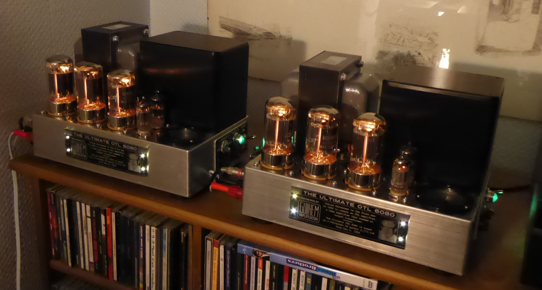
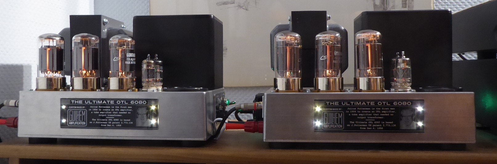
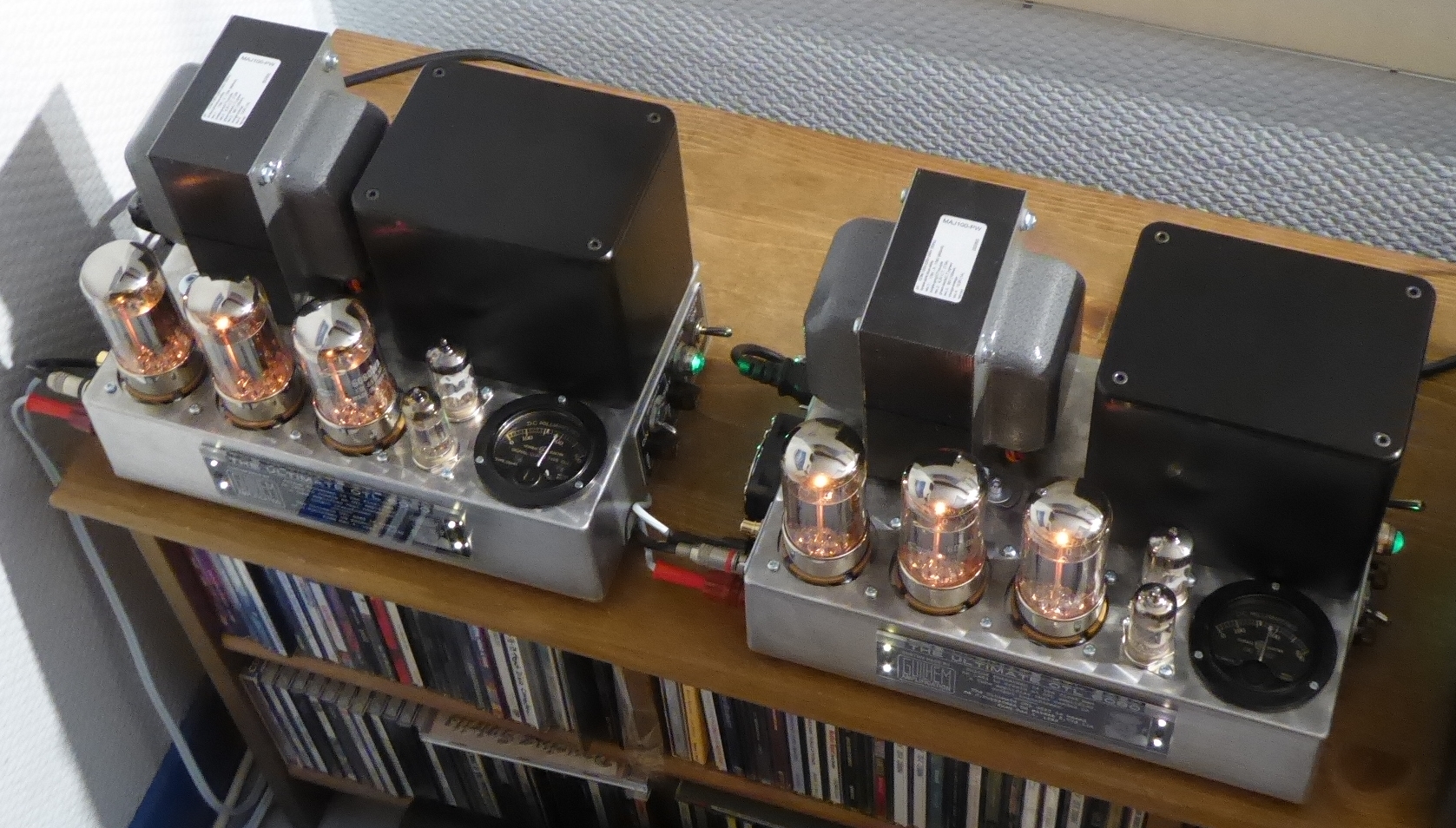
I needed a way to switch out the amps for a listening comparison along with being able to switch input devices. So I built a new entertainment ctr. Oh yeah, I tried to find one to buy, a corner unit with shelf spacing to accommodate the large, hot amps. I must be the only one that needed something like this - so I built one. It is .8 in hard maple and 1 in mahogany.
Using the Scott as a pre, for a while. Now I can continue my comparison, though the differences between the Futterman / Circlotron are more related to practicality and construction. I can tell you now they sound very similar. One other surprising observation is that my Lenovo (used as music server) sounds better than that Sony disc changer. Both have variable output not requiring a preamp.


Using the Scott as a pre, for a while. Now I can continue my comparison, though the differences between the Futterman / Circlotron are more related to practicality and construction. I can tell you now they sound very similar. One other surprising observation is that my Lenovo (used as music server) sounds better than that Sony disc changer. Both have variable output not requiring a preamp.
I am getting more IM distortion at higher frequencies than I would like. I am testing various 6SN7s as replacements for the GEs that are in the amp now. As to 6AS7s, is there a version that is known to produce less IM?
So the IMD varies with frequency? If yes, not something I've encountered before.
Is the load impedance lower or higher at those frequencies and what frequencies are we talking about?
Is the load impedance lower or higher at those frequencies and what frequencies are we talking about?
I am using the 2-tone test where the Upper tone's amplitude is 25% of the lower tone. The tones are 60hz and 3khz. The upper tone is distorted by the lower tone.
Feedback resistor changed from 2megs to 100k removes 95% of the distortion. Lower than that removes most of the gain.
I am using an 8ohm speaker as a load rather than a resistor, but switching to a 8ohm resistor does not change it much.
Clarity in the upper octaves is improved greatly with more FB.
Russ
Driving a 38 Ohm Headphone with a 6N1P OTL.
Amazing!
Is there anything special or unusual about the circuitry or parTh
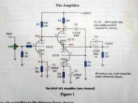
There isn't anything special about the circuit, it is very simple, it's just a standard triode gain stage directly coupled to the grid of a White Cathode-Follower output stage that's been modified so it is balanced properly, here's the schematic, the value of resistor R4 (200 Ohms) has been chosen so that the triode in the top half of the White Cathode Follower has a voltage gain of 1, the signal is AC coupled from pin 1 to pin 7 via a .470uF/400V cap, the two triodes act like a push-pull output stage, and the signal on pins 3 and 6 is AC coupled to the headphones via two 220uF/250V caps in parallel, since the top triode in the White Cathode output stage also acts as a cathode-follower, or common anode amplifier, it provides a low output impedance.Driving a 38 Ohm Headphone with a 6N1P OTL.
Amazing!
Is there anything special or unusual about the circuitry or parts?
Attachments
Driving a 38 Ohm Headphone with a 6N1P OTL.
Amazing!
Is there anything special or unusual about the circuitry or parTh
Here you go, here's a link to my thread: https://www.diyaudio.com/community/...ifier-using-three-svetlana-6n1p-tubes.416152/DrNomis44,
You could have referenced your other Post # about your amplifier that is in your other thread in Tubes / Valves.
That thread would allow me to answer the question I posted in Post # 1,165 in this thread.
Thanks!
Check out this website article, it goes into more detail on how the circuit works: https://headwizememorial.wordpress.com/2018/03/20/the-morgan-jones-mini-tube-headphone-amplifier/Driving a 38 Ohm Headphone with a 6N1P OTL.
Amazing!
Is there anything special or unusual about the circuitry or parts?
WRT an OTL driving a speaker as the one mentioned the issue is whether or not the amp uses enough feedback to behave as a Voltage source, (which in the case of our OTLs they don't) and whether the speaker is intended to be driven by a Voltage source (which most are). If you have a speaker that was made prior to the adaption of the Voltage rules (perhaps an Altec from the 1950s) then its using the Power rules instead. Such speakers are rare today but they do exist. So in your scenario, the question is whether or not the amps and speakers are playing by the same rules. If they are no worries, if they are not you will get a tonal imbalance. You can read more about this here.
You wrote:
"Specifications of amplifiers measured under the Voltage Paradigm will not tell you anything about the way that amplifier sounds. It is very easy to tell how an amplifier will sound using measurements based on the Power Paradigm as the measurements are made with regards to understanding and working with the rules of human hearing."
This is tantalizing, but you left us hanging by a thread here.
(1) What are the Power Paradigm Measurements?
(2) What are the Voltage Paradigm Measurements?
(3) How is the Power Paradigm correlated to how we hear?
I can guess that it's related to the spectrum of harmonic distortions, ignoring THD. But, still, it would be nice to hear from you.
We do love how negative 2nd harmonic sounds...
Best way to find out how an amp sounds subjectively is to play music through it and give it a good listen, subjectively, I think my OTL Headphone amp build sounds wonderfully pleasant to listen to.
Nothing special or unusual about the parts I used, which were all standard electronic components you can buy online, resistors were 5%/1W and 5%2W Metal Oxide types, nonpolarized caps were standard yellow RT metalized polymers rated at 630V DC, the other caps were standard RT types rated at 25V DC, and 63V DC, the output caps are standard RB can types rated at 450V DC, the main +HT filter caps are standard dual can caps rated at 500V DC, the tubes I used were three brand new Svetlana 6N1P medium mu (33) dual triodes, the three 9-pin sockets I used were standard Belton types, I used a standard Alpha 24mm dual-gang 100k log pot for the volume control, I used gold plated RCA sockets for the inputs, I used a standard 1/4 inch stereo Cliff Jack for the headphone out socket, a standard Hammond 369AX power transformer, a standard 3AG panel mount fuse holder, a standard 240V AC 3-pin plug and 2m of standard 240V AC 3-core mains lead, no special "unobtanium" parts were used at all.Driving a 38 Ohm Headphone with a 6N1P OTL.
Amazing!
Is there anything special or unusual about the circuitry or parts?
We do.You wrote:
"Specifications of amplifiers measured under the Voltage Paradigm will not tell you anything about the way that amplifier sounds. It is very easy to tell how an amplifier will sound using measurements based on the Power Paradigm as the measurements are made with regards to understanding and working with the rules of human hearing."
This is tantalizing, but you left us hanging by a thread here.
(1) What are the Power Paradigm Measurements?
(2) What are the Voltage Paradigm Measurements?
(3) How is the Power Paradigm correlated to how we hear?
I can guess that it's related to the spectrum of harmonic distortions, ignoring THD. But, still, it would be nice to hear from you.
We do love how negative 2nd harmonic sounds...
Did you read the article at the link of my post you quoted?
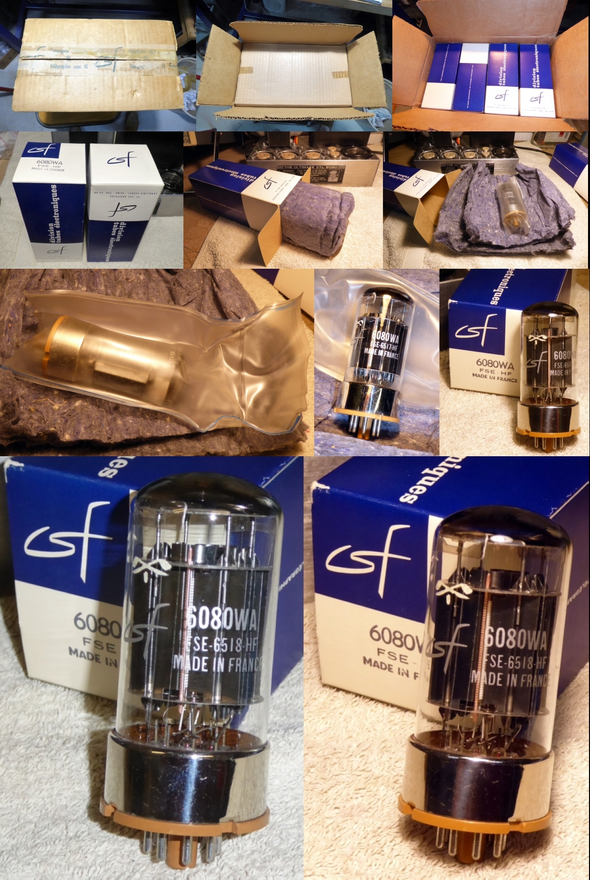
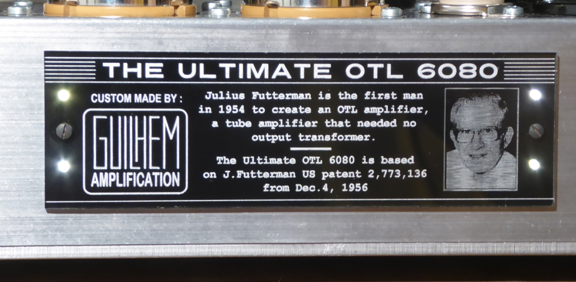
They are so cute! Julias was not the first to design on OTL though. He was the first to produce one commercially.What tubes for a OTL tube amp?
I still rely on the faithfull 6080WA :
- Home
- Amplifiers
- Tubes / Valves
- What tubes for a OTL tube amp?