Brilliant pots, no switch noise due to "S" type contact.🙂Like this one : HI-END??????????????DA*T??AL*S???20mm??-??? ?
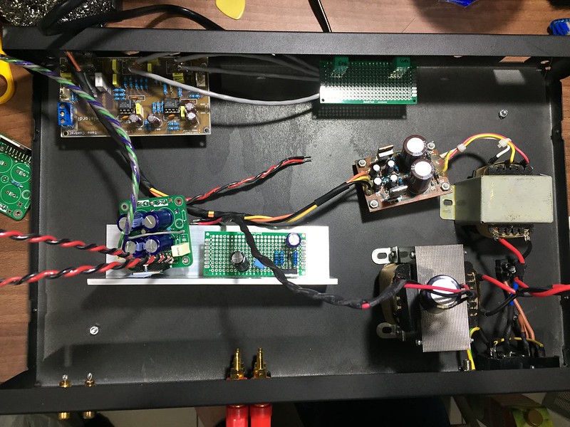
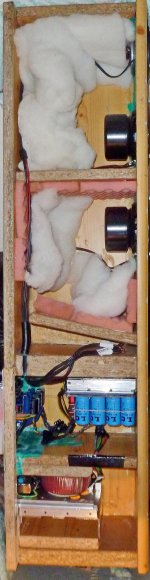
Folks, I am making an enclosure for my TDA7297 amp. Can you comment on my layout, one that brings as little interference/noise as possible. 🙂
Fiber board is the tone control, and the bass/treble pots to the right.
Big trafo powers the power amp, small trafo and the rectifier board feed the tone control.
Capacitance multiplier will be installed on the same heatsink as the power amp. It's based on Juma design, but I build a new one using IRF540 and 10x1000uF/16V caps. Previously I used IRF610 with 4700uF/25V cap at the output. 🙂 🙂
Hi people,
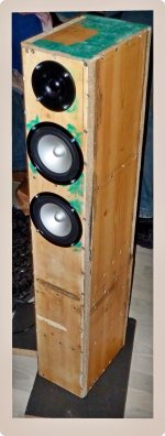
tonight I could try out my first box for the first time. It's not finished yet, and it looks pretty shabby because I'm on the lowest budget you can imagine, but it worked on 1st try and it sounds great!
For the moment I'm just using two of the three LM1875, because it has been weeks I was without music and so I just put a high pass capacitor in front of the tweeter. It will be activated in the next days.
It's 2.5 way all managed by Equalizer APO, one closed enclosure 8l for the first 5" and the tweeter, and 8l BR for the "half" way, the second 5".
It's still much work, but I'm really happy!
Attachments
-
 ELKO Aufhängung 800w 01.JPG496.4 KB · Views: 547
 -
 Q.C. passed 800w 01.jpg172.8 KB · Views: 658
 -
 Amps Elkos & Trafo 600w 01.JPG553.9 KB · Views: 552
 -
 Amps Elkos & Trafo 600w 04.jpg614.6 KB · Views: 270
 -
 Die Spannung steigt 800w 01.jpg399 KB · Views: 248
 -
 Fellatio 01 800w.jpg526.4 KB · Views: 268
 -
 van hinne 800w 03.jpg452 KB · Views: 245
Last edited:
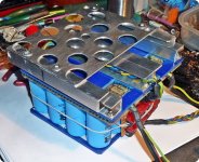
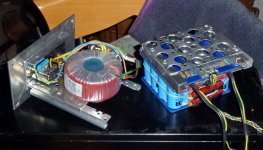
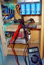
Impressive! That's what I call a capacitor bank. Sturdy construction. Congratulations.
Last edited:

Normally I couldn't afford these capacitors, but I was really lucky and shot 100 of these 4700µF/35V for 11,50€ at the bay.
12 Euro-cents a piece, that's a bargain.
Hi guys, I know the datasheet says voltage rating is 6-18VDC and absolute maximum is 20V. Does anyone use 19V laptop power supply for continuous use? Thanks.
If it is the China board then I wouldn't run over 12v if you want it to last more than a week.
Otherwise if it is a chip that you got from an electronics distributor, try it. I have run one over a week at 22v. It is hard to tell how long they will last past 18v.
Otherwise if it is a chip that you got from an electronics distributor, try it. I have run one over a week at 22v. It is hard to tell how long they will last past 18v.
Hi guys, I know the datasheet says voltage rating is 6-18VDC and absolute maximum is 20V. Does anyone use 19V laptop power supply for continuous use? Thanks.
I am not convinced that China items will do significantly worse than non-China items. After all, where are the wafer houses, used by well known brand owners, located? This is no high tech item.
Anyway, why not give it two ordinary 5A diodes in series and a 2200uF for decoupling when using 19V?
The eBay boards rate them at 12vdc now because so many boards failed above that but below 18v.
Fair enough, you have information I do not have.
Sometimes I feel that "China boards" are (unfairly) seen as plainly fraudulent items that cause nothing but trouble. This is not my personal experience.
Sometimes I feel that "China boards" are (unfairly) seen as plainly fraudulent items that cause nothing but trouble. This is not my personal experience.
I ran mine at 16V, 18V, 19V, laptop ps for a few weeks and it was fine. The heatsink gets damn hot (can't touch for more than 3 sec) when running at 19V so make sure it's got lots of ventilation or a little fan.
Still a fun little amp on my pc speaks, kit sys and others for the past few years. And hey, it's less than lunch! 😉
Still a fun little amp on my pc speaks, kit sys and others for the past few years. And hey, it's less than lunch! 😉
The chips and tolerance of voltage are random from Chinese eBay sellers.
The problem isn't the heat tolerance typically, it's that the insulating materials and types of silicon switches can degrade too rapidly from the voltage. Well, sometimes it's a mix between voltage and the current required with it, as the current can cause migration and the small conductors can develop cracks & humps. In that case the heat matters, but the problem is you can't sink it away fast enough internally of the chip. The limits are usually adjusted for long term use and found in the spec sheet. But the Chinese eBay boards are chips that likely didn't pass testing at their rated specs. Why they didn't pass can vary, and so likely will their ability to handle voltages.
The problem isn't the heat tolerance typically, it's that the insulating materials and types of silicon switches can degrade too rapidly from the voltage. Well, sometimes it's a mix between voltage and the current required with it, as the current can cause migration and the small conductors can develop cracks & humps. In that case the heat matters, but the problem is you can't sink it away fast enough internally of the chip. The limits are usually adjusted for long term use and found in the spec sheet. But the Chinese eBay boards are chips that likely didn't pass testing at their rated specs. Why they didn't pass can vary, and so likely will their ability to handle voltages.
Thanks guys I understand there is a potential risk. I got the chip new from a reputable supplier. Which setup will give me more punch and output:
19V to IRF540 based cap multiplier with 6000uF on the board, or
19V to a big cap, say 22000uF 25V.
Thank you!
19V to IRF540 based cap multiplier with 6000uF on the board, or
19V to a big cap, say 22000uF 25V.
Thank you!
A capacitance multiplier with IRF540 (N-channel) will require a gate-source voltage of some 4-5V thereby reducing the (output) supply voltage to 14-15V. Less heating but also less power.
More "punch and output" is your second suggestion. Use at least a large heatsink. Any large aluminum profile should do.
More "punch and output" is your second suggestion. Use at least a large heatsink. Any large aluminum profile should do.
Use a simple rectifier diode and a cap (D-C). A diode will drop the 19V a bit (up to 1V under load), and a big cap will add cohones and better peceived "detail"; whatever this means to you. (I use this approach myself).
I would also say that using a couple low-ESR caps in parallel works better than one large one. My suggestion is 2x 10.000uf + 1x 4700uF, all rated 25V.
But first you must be sure that your laptop PSU handles all this capacitance without hiccups at power-up! IF IT DOES NOT; your best option is imho using a "slow starting" capacitance multiplier, but with a darlington transistor - NOT a mosfet. Try a BDX53.
- Home
- Amplifiers
- Chip Amps
- What the heck? It's less than lunch!