Please, I need to see board layout.
Here we go:

Please let me know what you think, and what I should do. Thanks mucho.😉😉
Run a wire from the mini-jack ground to the ground on the DC input wires. It should turn on then.
Run a wire from the mini-jack ground to the ground on the DC input wires. It should turn on then.
Sure enough, that did it.

Thanks so much Jeremy, for sharing your insight and experience. I know you had to go thru a lot of experiment to find this when you were designing your board. So thanks for that.
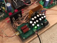
Some eye candy (at least to me they look beautiful 😉)


Ya, my first PCB board wouldn't turn on either... I even soldered in a new chip; what a headache. My friend who's real smart had no idea either. So I studied the other boards and noticed they all shared that. And it worked!
Sure enough, that did it.
Thanks so much Jeremy, for sharing your insight and experience. I know you had to go thru a lot of experiment to find this when you were designing your board. So thanks for that.
Some eye candy (at least to me they look beautiful 😉)

Nice work making your own board! Having good and big input caps makes a difference. I am using 2.2uF MKT 400v ones from CBB. They are pretty inexpensive but sound good.
Update on Folsom amp
I noticed the little stock heatsink could not keep up with a 17v TL431 shunt regulated power supply that the Folsom amp comes with. It gets toasty hot. I took a $1 CPU fan cooled heatsink and added a 2w 100R resistor between it and a 7812 voltage regulator connected to the PSU upstream of the shunt regulator. This setup slows down the fan significantly to inaudible but still effective for heat removal. Heatsink is now barely warm. I put the board on a wooden block for a base and added some 5 way banana speaker binding posts for easy connection. I almost fully populated the cap bank on this board so that the supply rail is very low ESR. Bass transients are very snappy and deep. Mids and highs sound great. Really like how compact this set up is. It's quite deceiving how powerful of an amp it is - I have not stress tested yet but imagine 28 to 30w should be no problem. I have the full blown Folsom power supply with a 100w toroidal trafo but recently using a 24v 5amp SMPS which I think sounds fine for a basic setup.
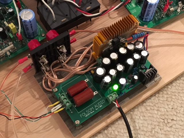
I noticed the little stock heatsink could not keep up with a 17v TL431 shunt regulated power supply that the Folsom amp comes with. It gets toasty hot. I took a $1 CPU fan cooled heatsink and added a 2w 100R resistor between it and a 7812 voltage regulator connected to the PSU upstream of the shunt regulator. This setup slows down the fan significantly to inaudible but still effective for heat removal. Heatsink is now barely warm. I put the board on a wooden block for a base and added some 5 way banana speaker binding posts for easy connection. I almost fully populated the cap bank on this board so that the supply rail is very low ESR. Bass transients are very snappy and deep. Mids and highs sound great. Really like how compact this set up is. It's quite deceiving how powerful of an amp it is - I have not stress tested yet but imagine 28 to 30w should be no problem. I have the full blown Folsom power supply with a 100w toroidal trafo but recently using a 24v 5amp SMPS which I think sounds fine for a basic setup.
Attachments
Ya, my first PCB board wouldn't turn on either... I even soldered in a new chip; what a headache. My friend who's real smart had no idea either. So I studied the other boards and noticed they all shared that. And it worked!
Is that some sort of sense wire to get the soft start internal to the chip to trigger on?
Is that some sort of sense wire to get the soft start internal to the chip to trigger on?
If I could track down the designer of the chip... 😛
Stress tested with 5R power resistor able to get 11v RMS before clipping. About 24watts. Response was flat from 20Hz to 20kHz varied 10.6v to 11v.
Stress tested with 5R power resistor able to get 11v RMS before clipping. About 24watts. Response was flat from 20Hz to 20kHz varied 10.6v to 11v.
Was this driving one channel only? The datasheet specs are 2 amps output current max. I assume this is total for both channels. I always wondered if one could get twice the output power using one channel per chip and two chips.
Just one channel so if both going it would be about 50w total power. The fan cooled heat sink works wonders. Chip barely got warm - whereas the shunt regulator transistor (now fitted with the huge stock lunch money amp heatsink gets really hot since it had no fan).
This amp is not bridged so you could bridge it in parallel (I have done so before) simply by tying outputs together and tying inputs together with two input 4.7k resistors in a Y to the source. I suppose that's going to get you 50w into 4ohms.
This amp is not bridged so you could bridge it in parallel (I have done so before) simply by tying outputs together and tying inputs together with two input 4.7k resistors in a Y to the source. I suppose that's going to get you 50w into 4ohms.
Last edited:
xrk971 I would repeat the test with a resistor on both channels to confirm that it can do that power on both channels or total.
If you get a lower number it'll tell us that the benefit would be in using two chips, and one channel at a time. If it remains the same then parallel may have benefits for actual power; but not necessarily quality of sound.
If you get a lower number it'll tell us that the benefit would be in using two chips, and one channel at a time. If it remains the same then parallel may have benefits for actual power; but not necessarily quality of sound.
Nice work making your own board! Having good and big input caps makes a difference. I am using 2.2uF MKT 400v ones from CBB. They are pretty inexpensive but sound good.
Thanks for your kind words and your help too. I have another board like this, maybe I'll do it differently 🙂
This one still has a faint ringing, I wonder if using a bigger mute cap will take care of it, or is there a bypass cap I can use, maybe it's radio frequency it's picking up?
If anybody would come with a point to point tutorial, I think that would be nice as well seeing how few components we actually use.
xrk971 I would repeat the test with a resistor on both channels to confirm that it can do that power on both channels or total.
If you get a lower number it'll tell us that the benefit would be in using two chips, and one channel at a time. If it remains the same then parallel may have benefits for actual power; but not necessarily quality of sound.
Ok I will round up a few more power resistors and repeat the test with both channels.
- Home
- Amplifiers
- Chip Amps
- What the heck? It's less than lunch!