I don't think these chips are sub-standard, just assembled in different plants. Don't forget that STMicroelectronics is Europe's largest semiconductor manufacturer With an annual turnover of 10 billion US$. They are not a mickey mouse outfit.
I had one that blew/doesn't work by using a 16v SMPS that might of spiked to 18v?
My other one works fine.
My other one works fine.
I have been running my amp with an inexpensive LM338 board adjusted to 18v without problems.I had one that blew/doesn't work by using a 16v SMPS that might of spiked to 18v?
My other one works fine.
I'm guessing you have 4 Ohm speakers?
What about those 126ens, could they be Chinese fakes?😀126en's, so no.
Guess it was a reject!
What about those 126ens, could they be Chinese fakes?😀
Only if they're still better than the 126 and 108 sigma... So I wouldn't care!
Don't you think it funny? Every time somebody on this forum builds an amp that doesn't work as expected, it's always blamed on fake or rejected chips.
Don't worry about importing diseases from Asia when we have plenty of home grown diseases of our own.
But then a lot of us have actually tested it so while it could be assembly errors, there is no doubt with 100% certainty there are sub par chips out there. The only question is relative percentages i.e. 30% of the kits are put together wrong and 10% of the chips on eBay are fakes.
I actually built a test fixture back in the day for a 14 pin dip. Some of the chips from certain suppliers were 100% failures. Understand all I did was take the chip out of the packaging and plugged it in to a circuit board. They were not little errors like a bit to much distortion but right out of the box, some stereo amps had at least one if not both channels busted.
I just went though this again in that TDA2030 thread. The chips that came with the kit both failed at anything near their recommended voltage. Replaced both chips with TDA2030, TDA2040, and LM1875. All chips from the alternate supplier worked fine which kind of eliminates the chance of operator error.
I wasn't the only one testing either. They failed on several counts.
I received my boards 😀
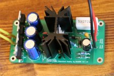
I populated one set and sang at first try. I'm feeding about 16V on each rail.
Sounds very nice but I didn't have the time to do proper listening. Also I want to measure the supply for noise and ringing. I did not install the snubber capacitor yet, and the LED I chose seems real bright so I had to disconnect it at the moment. I will try less current.
I've used a LM338 but I will replace for LT1084/LT1085. I'm using a 16VAC/5A transformer. The amp definitely has more omph than the ta2020.
* I noticed that I've installed 25VDC capacitors on the PS. I must have mixed them for the amp ones last night as I was tired. 25V capacitors with 16VAC supply is right on the edge. The ones from the amp are rated at 35V so I will swap them later today. So it seems I did make a mistake 🙂
Attachments


Last edited:
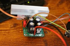
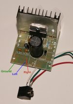
oops- I forgot to ask if I'm right to connect the 3 wires to the front 3 holes on the board and ignore the others 😕😱
I am putting together this little kit and need some help for wiring up the audio in.
Any help would be most appreciated 😀
oops- I forgot to ask if I'm right to connect the 3 wires to the front 3 holes on the board and ignore the others
cheers
Attachments
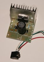
Thanks kja- but that side is for the pot. The right side is for input.
cheers
Sorry, I assumed you were not using an on board pot since it was removed.
My diagram is correct if you are using the 7297 as an amp with no on-board pot.
Hi kja- I hadn't put the pot on the board when I took the pic. my bad
I'm not sure the three wires of the input go.
cheers
I'm not sure the three wires of the input go.
cheers
Hi kja- I hadn't put the pot on the board when I took the pic. my bad
I'm not sure the three wires of the input go.
cheers
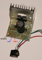
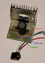
Follow the traces on the back of the board to these spots where the pot is installed.
Attachments

I thought it would look something like this 😕
No, more like this.... double check to see that the traces on the bottom are like I've shown
Attachments
Yes, your TDA7297 could do dynamic peaks at 60 watts total system power, and the Class D chip will not be doing that. While driving your 4 ohm speakers, it might be more kindly to dial the power voltage down to 13.5vdc or less. With the TDA7297 chip, the actual voltage (that we should be using) could probably align like you're trying to Avoid activating the 2a limiter, except for very brief transient surges. However, 4 ohm speakers aren't mentioned in the datasheet so I don't know what the perfect operating voltage would be in that case. We do know that 16v is too high in this case. The 13.5vdc when driving 4 ohms, is really just a guess but it is in generally the right direction. 🙂The amp definitely has more omph than the ta2020.
Last edited:
- Home
- Amplifiers
- Chip Amps
- What the heck? It's less than lunch!