TRANSFORMED.
Hi,
Because I feel people like to think that it would be a great idea to have the universal powerxformer defined.
You, others and yours truly know that you can't just do that, we're a tad wiser than that.
So in conclusion that is indeed wishful thinking...just as thinking that the best core material will make for the best powerxformer.
It doesn't work like that at all.
Defining more or less important design factors for a powerxformer will grossly depend on what it has to do, i.e. the task at hand.
While I understand the goals Nania wants to set, I also understand the limiting factors involved.
When it may be absulutely correct that the regulation capability of a xformer is of limited significance in a preamp it may well be crucial for a poweramp, so there we go.🙄
Cheers,😉
Hi,
I wonder why people thing design choices are so easy and cut and dried. Wishful thinking and a lack of willingness to do even the most basic research seems to be the order of the day. I will leave you in more capable hands but don't confuse motion with progress.
Because I feel people like to think that it would be a great idea to have the universal powerxformer defined.
You, others and yours truly know that you can't just do that, we're a tad wiser than that.
So in conclusion that is indeed wishful thinking...just as thinking that the best core material will make for the best powerxformer.
It doesn't work like that at all.
Defining more or less important design factors for a powerxformer will grossly depend on what it has to do, i.e. the task at hand.
While I understand the goals Nania wants to set, I also understand the limiting factors involved.
When it may be absulutely correct that the regulation capability of a xformer is of limited significance in a preamp it may well be crucial for a poweramp, so there we go.🙄
Cheers,😉
Re: TRANSFORMED.
Regulation has to do with the quality of a transformer (and correct application) and is an important issue even when applied to line amps.
Regulation implies you have headroom and it's important in the way the trafo accepts or tolerates some DC on the primary without been througn into saturation.
Same thing for poweramps in its own proportion. So in my view, right on track....
fdegrove said:
When it may be absulutely correct that the regulation capability of a xformer is of limited significance in a preamp it may well be crucial for a poweramp, so there we go.🙄
Regulation has to do with the quality of a transformer (and correct application) and is an important issue even when applied to line amps.
Regulation implies you have headroom and it's important in the way the trafo accepts or tolerates some DC on the primary without been througn into saturation.
Same thing for poweramps in its own proportion. So in my view, right on track....
Okay, I still haven't a commitment on whether regulation is a derivative of the four original transformer parameters or one that should be added to make it five. Remember the focus here is to identify what physical characteristics are responsible for the sound characteristics we seek. Can regualtion be achieved without including any of the original four parameters? If the answer is yes, I will add it to the list and make it five. I leave it to the constituency to direct me. So far the only parameter put forth that was not contraversial in its negative effect on sound was lower core flux density, so we will look at this in greater detail.
1a. core size (bigger is better)
1b. core material (better saturation curve)
1c. windings (more turns are better)
1d. transformers in series
This list identifies the ways to achieve lower core flux density. If it is complete, we will begin to examine the sonic penalty for high core flux and where in the bandwidth these sonic penalties occur. Agreed?
Interestin' stuff
As is usual for Fred, there's some good stuff buried in this thread.
A few quick notes, with more detail later. I've done some work with snubbers for TX secondaries, and since the snubbers were derived by calculation I also did some measurements of capacitance and leakage inductance for a couple of transformers. It's pretty easy to do, if you have a inductance meter (one of those inexpensive DMM-types will do) and a suitable oscillator to derive the resonant frequency to enable stray capacitance to be calculated.
For information the resultant RF was anywhere between 700kHz and almost 2MHz, dependant upon transformer size - the bigger transformer (both toroids) had the higher frequency.
Capacitive 'snubbing' (which isn't that at all) doesn't work - it just changes (lowers) the resonant frequency of the resultant circuit, land may or may not make things worse dependant upon decoupling elsewhere etc.
Most electrolytics are pretty crap at 2MHz though 😉
An RC network is effective and cheap, although I've not ascertained substantial benefits in my albeit brief experiments. Reducing the RF generated must be a good thing though, if solely to prevent RF-induced non-linearities in equipment being powered.
Too much to do, so little time 😉
Andy.
P.S. A browse on the Plitron site and you will discover some interesting low-bandwidth transformers, that work by coupling secondaries capacitively, to form a low-pass filter in conjunction with transformer leakage inductance...I'm like Fred though and have a load of wide-BW toroidal-based PSU's that sound great

THE BANDWIDTH ISSUE.
Hi,
Regarding BW, not my experience though...
I'd like to limit bandwidth at the source as much as possible...
And I think Fred meant other apps not power XFs.
I always foound it easier to tackle problems at the source, not trying to cure them after the event.
Cheers,😉
/Listening to Emimen: Sing for the moment.
Love the guitar riffs.
Hi,
P.S. A browse on the Plitron site and you will discover some interesting low-bandwidth transformers, that work by coupling secondaries capacitively, to form a low-pass filter in conjunction with transformer leakage inductance...I'm like Fred though and have a load of wide-BW toroidal-based PSU's that sound great
Regarding BW, not my experience though...
I'd like to limit bandwidth at the source as much as possible...
And I think Fred meant other apps not power XFs.
I always foound it easier to tackle problems at the source, not trying to cure them after the event.
Cheers,😉
/Listening to Emimen: Sing for the moment.
Love the guitar riffs.
Bandwidth
I feel this has to be looked at in two ways - noise conducted into the device, and also out.
Line filters work well for both, but frankly suck, sonically IMHO.
The impedance of the mains supply, as transformed to the secondaries is VERY imporotant, in my experience.
Andy.
I feel this has to be looked at in two ways - noise conducted into the device, and also out.
Line filters work well for both, but frankly suck, sonically IMHO.
The impedance of the mains supply, as transformed to the secondaries is VERY imporotant, in my experience.
Andy.
XF.
Hi,
Simply put, the less in the better.
There you go...I never liked them, they soak up dynamics as expected.
And than what? High ? Low?
I agree that it is important but what's your experience?
BTW, FWIW, any half decent Xformer manufacturer will be able to make you a very good XF from what you want from it.
It may not be cheap, but defning criteria for the all in all XF is just impossible INHO.
Cheers,😉
Hi,
I feel this has to be looked at in two ways - noise conducted into the device, and also out.
Simply put, the less in the better.
Line filters work well for both, but frankly suck, sonically IMHO.
There you go...I never liked them, they soak up dynamics as expected.
The impedance of the mains supply, as transformed to the secondaries is VERY imporotant, in my experience.
And than what? High ? Low?
I agree that it is important but what's your experience?
BTW, FWIW, any half decent Xformer manufacturer will be able to make you a very good XF from what you want from it.
It may not be cheap, but defning criteria for the all in all XF is just impossible INHO.
Cheers,😉
fdegrove, ALW
Where did you get the notion that we are looking for the "one transformer" that will make great sound in any situation? I think that clear from the outset of this thread, we only wanted to identify which characteristics in a transformer are preferable and why they are so.
That said, the topic of muted dynamics is interesting since the power transformer is only responsable for providing enough charge to the supply caps as cleanly and unobtrusively as possible. I think the line filters and snubbers have more of an interactive issue with the supply capacitance than the transformer itself. Anyone else want to comment on this?
Anyone?
I want to, but I don't dare to........
nania said:fdegrove, ALW
Where did you get the notion that we are looking for the "one transformer" that will make great sound in any situation? I think that clear from the outset of this thread, we only wanted to identify which characteristics in a transformer are preferable and why they are so.
That said, the topic of muted dynamics is interesting since the power transformer is only responsable for providing enough charge to the supply caps as cleanly and unobtrusively as possible. I think the line filters and snubbers have more of an interactive issue with the supply capacitance than the transformer itself. Anyone else want to comment on this?
I want to, but I don't dare to........
pearly wisdom
Fred is in secretion mode and he's building up a nice lacquer on this subject. I am tempted to crack him open and look in wonder at what he has already but I may be better off waiting. If only there were a way to peek inside his crustaceous mind without disturbing it.
Fred is in secretion mode and he's building up a nice lacquer on this subject. I am tempted to crack him open and look in wonder at what he has already but I may be better off waiting. If only there were a way to peek inside his crustaceous mind without disturbing it.
How did I miss this rock throwing contest????
Probably the last time a professional transformer company completely ignored the specs I gave them.......i.e., the whole *******' desighn............, and I had to rebuild it to make it useable.
Is that what you wanted to know???
Jocko
By the way how long is it since you last roll yourself a pair of tranies for your DIY project?
Probably the last time a professional transformer company completely ignored the specs I gave them.......i.e., the whole *******' desighn............, and I had to rebuild it to make it useable.
Is that what you wanted to know???
Jocko
Musically Tuned PSU's ?.
Hi Phred,
In the context of power regeneration, you have made mention of using a large power amp to drive a step-up transformer in order to generate mains voltage to power standard 110V equipment.
You also make mention that 60Hz is better than 50Hz because of refresh rate, and consequent ripple.
IYO, would it be beneficial to run this 'mains' frequency at a rate related to the pitch that the music is played in ?.
Eric.
Well, its been a while with no activity so it seems that we are satisfied that the four original parameters mentioned in this thread are the only significant ones to consider when evaluating the potential effect on how it sounds. Of these primary four listed in numerical categories as:
1. core flux density (lower is better)
2. dc tolerance (higher is better)
3. quiescent current (lower is better or application specific)
4. wire thickness (thicker is better or application specific)
Of these four the least contraversial was the lower flux density. A list of ways we can achieve this lower core flux was submitted as letter enumerations on category 1. so that:
1a. core size (bigger is better)
1b. core material (better saturation curve)
1c. windings (more turns are better)
1d. transformers in series
If this list is complete, then we can go forward and make an analysis of the practicality and effectiveness of each method but before we do, we should discuss what sonic penalty we suffer with high core flux density and where we are likely to hear it. Is high core flux just muting dynamics or is some bandwidth limiting also happening?
Contributors are encouraged to put forward their experiences with problems caused by high core flux. Then we will compare which method would be best according to the flux problem observed.
Audio power xformer
In my experience, high flux density may cause problems with mechanical noises from the xformer. These can be quite audible during low-level passages.
So called "low noise" xformers are generally made by overrating the core. For instance, design a 300W xformer but use a core rated at 500W. I know at least one manufacturer of custom xformers (Burmeister in Germany) who does this and the results have been (for me) quite satisfying for a modest cost increase.
I have never experienced an effect on the audio signal itself related to flux (assuming the xformer has been mounted in a sensible position/orientation), so I would be interested in this. I always assumed that if this would be the case there was something seriously wrong with either the power supply design or the amp design.
Jan Didden
janneman
If we assume that flux saturation occurs only when the power delivery is stressed, then the power supply would not typically be stressed in low-level passages but perhaps it would in a class A design. Was your experience on a Class A amp circuit? Describe the noise as best you can. It's quite possible that the noise is also in the loud passages but masked.In my experience, high flux density may cause problems with mechanical noises from the xformer. These can be quite audible during low-level passages.
From the Institute of Electrical and Control Engineering© - go toWhat we need most in an Audio Power Transformer
Koinichiwa,
I have considered this in quite some detail.
1) Low Core Flux - This means using an oversized core and using more primary turns than commonly done, the result is a drastic increase in cost. A larger primary inductance also stores more energy to be released on the rectifier current peaks.
2) Ability to handle DC offset - many mains lines cary a distorted waveform, whose 2nd harmonic content causes a DC offset, which in turn causes some DC offset in the mains transformer core, which is usually already marginal in size to allow for high flux.
3) absolutely balanced winding arrangements with added electrostatic screens - using such arrangements will maximally surpress any common mode noise from the powerline and minimise leakage currents anywhere in the powersupply.
The result is a transformer that in terms of winding complexity, size etc approaches a good quality SE Output Transformer and will thusly also attract similar costs.
There are of course approaches that can be taken to minimise the problems caused by using normal commodity torroidal mains transformers. Such measures are often much less expensive than actaully having small series custom mains transformers made.
Such measures would include primary side common and differentail mode filtering of ultrasonic noise and DC blocking circuits in the primary. Also the use of mutiple identical transformers arranged CAREFULLY with regards to leakage capacitances to the chassis so that balance is attained can be applied.
Using compared to conventional rules heavily overdimensioned transformers can also be used to keep core flux down. A really freaky option is to use multiple transformers with arrangements of primaris and secondaries in series for halving the voltage across each winding. In this case just make sure that the transformers are sufficiently identical and that you always make one final winding up from equal sections of windings of the two cores, to make sure each core/transformer sees equal loads.
I personally feel that discussing and testing such means of better using commodity transformers is more beneficial for most cases where SS gear is concerend. This holds especialy true for most DIY'ers wish to keep costs controlled.
However, given that few companies make commodity priced mains transformers for Valve gear it would likely be of interest to develop better mains transformers for these applications, incorporating the above points. In such cases the cost penalty should be much more modest.
Sayonara
https://cn.nycu.edu.tw/en/research/...ronics-IC-Design-and-DSP-Control-Lab-85916011
and
https://en.wikipedia.org/wiki/National_Chiao_Tung_University
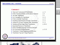
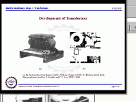
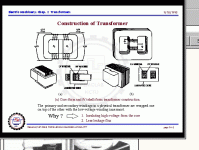
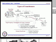
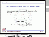
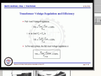
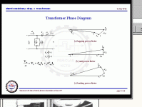
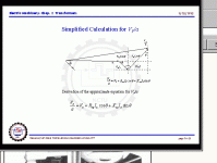
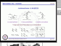
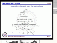
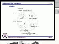
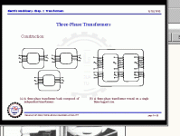
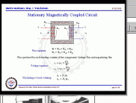
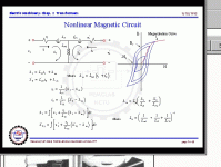
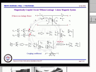
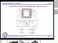
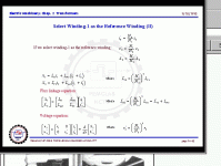
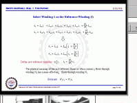
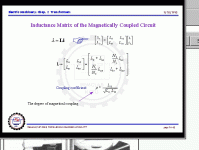
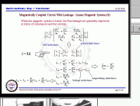
I have receive serial months ago a paper concerning basics of power transformers (maybe an excerpt of the book "ELECTRIC MACHINERY): Chap. 2 - Transformers (Ying-Yu Tzou, NCTU) - best basic description I know until now.
I receive each page as "GIF" file - unfortunately not to find as PDF like those pdf's to other subjects from the same institute:
https://ir.nctu.edu.tw/bitstream/11536/90000/1/9426237009006ET.pdf
https://ir.nctu.edu.tw/bitstream/11536/76223/1/753901.pdf
Thus I upload all 69 pages separately here (distributed in 5 posts).
In this case also this URLs are of interest:
Paul McGowan: High-End Survivor (Paul McGowan discusses the topic of large transformers)
https://www.stereophile.com/interviews/222/index.html
Explanation for Transformer Excitation Current
https://voltage-disturbance.com/power-engineering/transformer-excitation-current/
Modeling a real transformer: why is the excitation branch in parallel?
https://electronics.stackexchange.c...rmer-why-is-the-excitation-branch-in-parallel
Transformer-Brands: Toroidy (Poland) vs. Tauscher (Germany) and Plitron (Canada)
https://www.diyaudio.com/community/...-tauscher-and-plitron-who-have-tested.407349/
Easy find out ideal Values for Snubber Network to avoid ring-ring at Secondary Winding on Power Transformers
https://www.diyaudio.com/community/...rmer-snubber-using-quasimodo-test-jig.243100/
https://www.diyaudio.com/community/...inding-of-its-power-mains-transformer.408121/
Attachments
-
 sld001-Transformers.gif30.3 KB · Views: 58
 -
 sld002 Contents-I.gif31.7 KB · Views: 55
 -
 sld003 Contents-II.gif27 KB · Views: 60
 -
 sld004 Development Transf.gif45.4 KB · Views: 58
 -
 sld005 Construction Transf.gif34.4 KB · Views: 59
 -
 sld006 Power Gen.-Syst. Power Plant to consumer.gif31 KB · Views: 56
 -
 sld007 Types of Transf.gif34.1 KB · Views: 56
 -
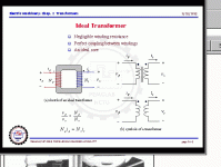 sld008 Ideal Transf.gif30.2 KB · Views: 52
 -
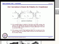 sld009 Dot marking for Polarity.gif39.2 KB · Views: 53
 -
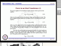 sld010 Power in an Ideal Transf.-I.gif29.9 KB · Views: 56
 -
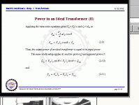 sld011 Power in an Ideal Transf.-II.gif26.8 KB · Views: 56
 -
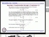 sld012 Impedance Transformation-I.gif30.5 KB · Views: 59
 -
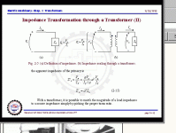 sld013 Impedance Transformation-II.gif33.1 KB · Views: 64
 -
 sld014 Equivalent Circuit of ideal Transf.-I.gif37.1 KB · Views: 54
 -
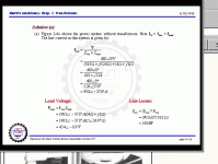 sld015 Analysis of Equivalent Circuit-a.gif28.4 KB · Views: 56
 -
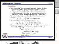 sld016 Analysis of Equivalent Circuit-b1.gif29 KB · Views: 60
 -
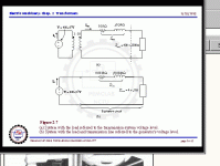 sld017 Analysis of Equivalent Circuit-b1-II.gif29.1 KB · Views: 51
 -
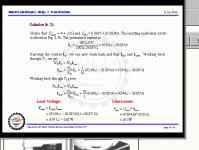 sld018 Analysis of Equivalent Circuit-b2.gif29.7 KB · Views: 66
 -
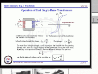 sld019 Operation of Real Single-Phase Transf.gif33.3 KB · Views: 51
 -
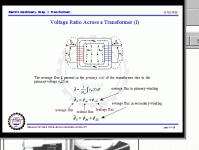 sld020 Voltage Ratio.gif31.2 KB · Views: 59
Chap. 2 Transformers 21-40
Attachments
-
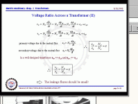 sld021 Voltage Ratio-II.gif31.1 KB · Views: 54
 -
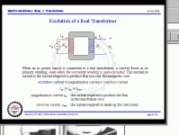 sld022 Excitation Current.gif35.8 KB · Views: 56
 -
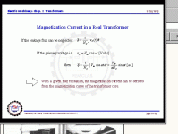 sld023 Magnetization Current-I.gif31.4 KB · Views: 57
 -
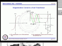 sld024 Magnetization Current-II.gif34.9 KB · Views: 49
 -
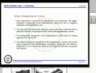 sld025 Magnetization Current-Notes.gif30.1 KB · Views: 55
 -
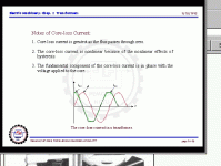 sld026 Core Loss Current - Notes.gif30.1 KB · Views: 55
 -
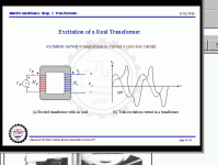 sld027 Excitation Current vs. AC Voltage.gif31.8 KB · Views: 57
 -
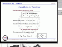 sld028 Current Ratio.gif29.7 KB · Views: 57
 -
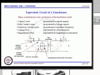 sld029 Modelling for Equivalent Circuit.gif33 KB · Views: 55
 -
 sld030 Real vs. Ideal Transf.gif31.4 KB · Views: 54
 -
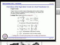 sld031 Derivation Equiv. Circuit Real Transf-I.gif32.4 KB · Views: 46
 -
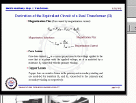 sld032 Derivation Equiv. Circuit Real Transf-II.gif32.9 KB · Views: 50
 -
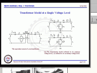 sld033 Transf. Model for single Voltage Level.gif31.2 KB · Views: 46
 -
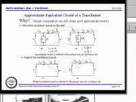 sld034 Approximate Equivalent Circuit.gif34.2 KB · Views: 53
 -
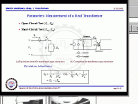 sld035 Parameters for Mesurement of a Real Transf.gif32 KB · Views: 53
 -
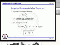 sld036 Parameters for Mesurement of a Real Transf-II.gif27.1 KB · Views: 50
 -
 sld037 Short Circuit Test-I.gif30.9 KB · Views: 60
 -
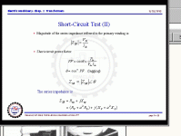 sld038 Short Circuit Test-II.gif27 KB · Views: 52
 -
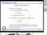 sld039 Short Circuit Test-III.gif26.8 KB · Views: 52
 -
 sld040 Per Unit System for Measurement.gif29.7 KB · Views: 58
Chap. 2 Transformers 41-60
Attachments
-
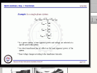 sld041.gif25.5 KB · Views: 55
 -
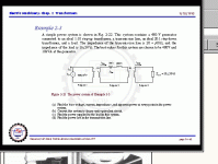 sld042.gif29.2 KB · Views: 54
 -
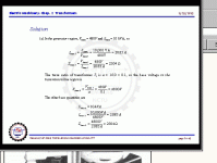 sld043.gif24.7 KB · Views: 55
 -
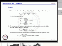 sld044.gif25.9 KB · Views: 58
 -
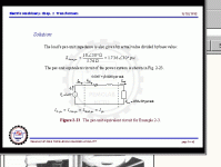 sld045.gif27.1 KB · Views: 55
 -
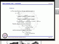 sld046.gif25 KB · Views: 54
 -
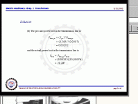 sld047.gif23.9 KB · Views: 60
 -
 sld048 Base Quantities for a Multiple Transf.-System.gif30.1 KB · Views: 53
 -
 sld049 Voltage Reg. and Efficiency.gif27.1 KB · Views: 50
 -
 sld050 Transf. Phase Diagram.gif28.6 KB · Views: 56
 -
 sld051 Simplyfied Calc for Vpa.gif25.1 KB · Views: 55
 -
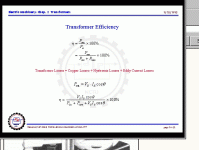 sld052 Transf. Efficiency.gif28.2 KB · Views: 53
 -
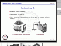 sld053 Autotransf.-I.gif48.2 KB · Views: 54
 -
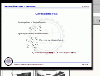 sld054 Autotransf.-II.gif28 KB · Views: 48
 -
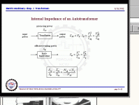 sld055 Autotransf. Impedance.gif26.5 KB · Views: 55
 -
 sld056 Autotransf. Relatinship Voltage to Current.gif32.3 KB · Views: 49
 -
 sld057 apparent power rating advantage of Autotransf.gif28.4 KB · Views: 53
 -
 sld058 apparent power rating advantage of Autotransf-II.gif24.9 KB · Views: 54
 -
 sld059 Three-Phase Transf.gif27.5 KB · Views: 54
 -
 sld060 Stationary Magnetically Coupled Circuit.gif33.8 KB · Views: 60
Chap. 2 Transformers 61-69
Attachments
-
 sld068 None Linear Magnetic Circuit.gif31 KB · Views: 62
 -
 sld067 Magnetic Circuit.gif31.7 KB · Views: 52
 -
 sld066 Equivalent Circuit Magnetically Coupled.gif32.8 KB · Views: 58
 -
 sld065 Select Winding-I as a Ref.-Winding-II.gif31.3 KB · Views: 55
 -
 sld064 Select Winding-I as a Ref.-Winding.gif30.2 KB · Views: 55
 -
 sld063 Stationary Magnetically Coupled Circuit-IV.gif30.4 KB · Views: 55
 -
 sld062 Stationary Magnetically Coupled Circuit-III.gif37.2 KB · Views: 50
 -
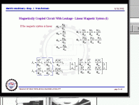 sld061 Stationary Magnetically Coupled Circuit-II.gif30.7 KB · Views: 54
 -
 sld069 last Page.gif24.8 KB · Views: 51
- Home
- Amplifiers
- Solid State
- What makes a good audio power transformer?